Solar thermal systems
Contents |
[edit] Introduction
The term 'solar thermal' (ST) is used to describe a system where the energy from the sun is harvested to be used for its heat. Solar thermal systems differ from solar photovoltaics which convert sunlight directly into electricity. The use of the term 'solar thermal' is also associated with the integration of 'passive' heating and cooling technologies in buildings.
The UK offers a good climate for solar thermal systems benefiting from around 60% of the solar energy that is received at the equator and similar amounts to other northern European states. The amount of solar radiation received (also known as 'solar insolation') is measured in kWh (kilowatt hours) over a particular time period. On a typical July day in Coventry there would be around 5 kWh of solar insolation.
Solar thermal systems are rated in kWth (thermal kW). The total of all solar thermal installations in the UK in mid-2010 was around 400,000 kWth.
The main application for solar thermal systems in the UK is domestic hot water heating although there are also 'combisystems' that use non-potable thermal stores directly linked with low temperature space heating (such as underfloor heating) and, in warmer climes, there are more technically challenging solar powered refrigeration systems.
A 2011 Energy Savings Trust report (Here comes the sun: a field trial of solar water heating systems) indicated that properly installed and operated systems can provide 60% of domestic hot water energy. Typical carbon savings from a well-installed and properly used system in a house amount to around 230 kgCO2/year when replacing gas and 510 kgCO2/year when replacing electric immersion heating.
[edit] The potential for solar heating in the UK
Solar thermal has had a great boost in recent times with the publicity around the Renewable Heat Incentive and the Green Deal, and as a result the adoption of solar collector technologies is gaining pace in the UK. Other European countries such as Germany, have seen a steady growth in the installed area of collectors since the early 1990s (so far around 10million kWth).
In the UK the average annual available solar irradiation varies between around 1,200 kWh/sq m on the south coast of England and up to 900 kWh/sq m in Scotland. Southern England has similar insolation to that in Holland, northern France and northern Germany. Solar data for the whole of the UK is available on the PVGIS Solar Map.
With only 55% of the sun’s light being visible, and much of the sunlight being diffuse there is potential for solar-powered water heating even on 'cloudy' days. A properly designed and installed solar thermal system can maximise the capture of this power and translate 60% of it into useful energy for hot water.
Solar systems have a number of positive attributes that are likely to promote greater use in the UK:
- They provide no exhaust gases (there may be some related emissions from pumping energy if this is necessary).
- Good quality collectors will have a life of 20 to 30 years.
- They offer long-term independence from fuel price inflation.
- Total cost analysis is largely based on the known, initial capital cost.
- Low maintenance.
- Potential for government subsidies.
- Certainty of fuel supply.
- They can improve the environmental credibility of building.
[edit] Government funding
All solar thermal installations of 45 kWth capacity or less need to be certified under the Microgeneration Certification Scheme (MCS or equivalent) to be eligible for financial assistance from the government. This provides a safeguard against poor quality and inefficient installations. Both the technology and the company or person installing the system needs to be certified under the MCS scheme. When applying for financial support, details of MCS certification will be required. For solar thermal installations larger than 45 kWth, Ofgem will verify eligibility.
The Solar Keymark is a quality label for solar thermal collectors and systems that fulfil minimum requirements according to specific European standards. It is recognised in the UK as equivalent to MCS for equipment, the installer still needs to be MCS certified.
Solar thermal panels for commercial hot water installations up to 200 kWth are eligible for the Renewable Heat Incentive (RHI). Domestic installations are expected to be included in the RHI scheme in 2014.
The Enhanced Capital Allowance (ECA) scheme enables businesses to claim 100% first-year capital allowance on investments in eligible solar thermal equipment against the taxable profits in the period of investment. However since the 2012 budget this provision is being phased out in recognition of the RHI.
NB The Renewable Heat Premium Payment scheme closed in May 2015.
[edit] Efficient solar thermal systems
The key for efficient system sizing is to meet as much of the annual domestic hot water requirement as is economically possible. This is known as the solar fraction and ranges from zero, for no solar energy use, to 1 to that indicates all the heat for the annual domestic water requirements is supplied by solar energy. The solar fraction of a particular system is dependent on many factors such as the load, the collector and storage sizes, the operation, and the climate.
Experience from Germany where there is a very mature market shows that systems are commonly oversized, having been based on assumed hot water consumption that is much higher than reality. Typically in summer the hot water usage was not reached and the expected solar insolation was exceeded. Combined with poor materials this led to overpriced, oversized systems that failed to meet expectations. Problems also arose in many cases due to poor integration with existing traditional hot water service systems. In the UK it should be reasonable to expect a solar fraction of 60%.
It is also important that when the system is designed it is able to deal with stagnation of water in the collector. This is the point at which the water system cannot accept all the heat from the collectors and so the heat from the sun may raise the temperature of the solar collectors well beyond 100°C, causing evaporation inside the system. Long periods of stagnation may be a sign of an over-estimation of solar fraction, where solar collectors are too large (and uncontrollable) for the their particular application.
[edit] Sizing solar thermal hot water systems
The method for sizing a solar thermal system is quite different to gas, oil or electric hot water systems. Conventional systems are sized based on peak hot water demand with additional capacity to provide potential for future expansion and safety margins.
A solar powered system would normally be sized so that it does not provide any more energy than is required to recharge the store of hot water in periods of low demand. This is normally a summer condition. A larger store may allow a greater solar fraction but an oversized store will mean that at times of low solar availability, stored water temperatures may be too low (at additional cost and space). The UK Building Regulations require that the store should be at least 80% of the daily hot water demand or 25 litres for every sq. m of collector area.
Practically, where systems are being installed in existing buildings, the capacity can be based on measurements of actual demand taken in periods of low consumption in summer. In new buildings they can be sized based on measured data in similar buildings.
There will almost certainly be a need to provide an auxiliary means of heating the water (normally from the main heating systems) for when demand cannot be met by solar collection. In this case, the solar hot water can be used as a means of preheating water that is subsequently fed into a separate continuous-flow water heater or a traditional hot water calorifier/cylinder. Purpose made cylinders are frequently used where a solar coil takes up the lower space in the cylinder and a traditional primary heating coil is in the top half.
Energy used in pumping can be significant, and so it is important to minimise pressure drops in systems through careful pipework design and by exploring the use of solar powered pumping.
The means to prevent legionella must be carefully thought through as poor scheduling of 'pasteurisation' cycles can reduce the opportunity to capture heat from the sun. The high temperature water can be circulated around the tank, but this will break up the temperature stratification (that would normally leave cooler water at the bottom) making the solar coil less effective.
[edit] Collecting solar heat
The selection of the type of collector will depend, amongst other things, on its temperature in operation and application. Collectors have several elements that combine together to ensure a consistent performance and longevity, including:
Basic operation is reliant on the 'green house effect'. Incident (high energy, short wavelength) solar radiation passes through the transparent or translucent surface of the solar collector and heats a metal or plastic surface. The glazed panels reduce the heat re-radiated back out and will also reduce convection of heat from the hot absorbing surface.
Unglazed (flat plate) solar collectors are used for low temperature water applications (such as swimming pools) where the loss of heat will not be as significant as with higher temperature panels.
[edit] The solar collector
There are two main types of solar thermal collectors currently used in the UK:
- Flat plate collectors.
- Evacuated tube collectors.
There are a number of variants of these in various materials, with the choice driven by the temperature of operation and the location and available area for mounting the panels.
Both types of absorber can reach high temperatures in operation and so must be properly constructed to maintain a long-lasting, consistent heat transfer between the absorbing surfaces and the tubes/channels through which the fluid flows that carries the heat to the hot water store. The collector must comply with BS EN 12975 - Thermal solar systems and components
[edit] Unglazed flat plate collectors
Unglazed panels are used where the required water temperature is no greater than 10K above the temperature of the air around it. This is suitable for swimming pool applications but not appropriate for domestic hot water systems.
[edit] Glazed flat plate collectors
Image: Flat plate collector
Glazed flat plate collectors are most suitable where the water temperature is between 10 and 50K above the surrounding air temperature, and so are ideally suited to domestic hot water applications.
The typical construction of a glazed flat plate collector comprises a lightweight metal or polymer tray that contains a layer of insulation (normally glass fibre) to prevent heat loss via conduction through the rear of the collector. The 'absorber' is designed to maximise solar irradiation absorption and is likely to have selective surface coatings to maximise solar gain and minimise re-radiation. For metal absorbers black chrome or nickel coatings are typically used.
A series of waterways bonded to the absorber carry the heat transfer fluid (water or glycol mix) through and away from the collector. The collector has a transparent glass or plastic cover across the whole 'aperture' with a low thermal expansion coefficient and high transmission efficiency to maximise net incoming solar radiation and minimise convection losses. Transmission efficiencies for good quality products are over 90%, absorption efficiencies 95%, emissions (losses) 5% and maximum thermal efficiencies of around 78% over the year.
Copper is commonly used for the tubing in the collector and aluminium or copper for the absorber sheets (with stainless steel being used when aggressive mediums flow through the absorber as in direct-fed swimming pool panels). Polymer and butyl rubber materials are used for applications where the system is designed to carry plain water that may freeze. Whatever tubing is used there must be a good thermal bond between the tubing and the absorber plate. Any connections to the panels together with the immediate fluid loops are likely to be made using mechanical joints rather than soft solder or even brazing as they are subject to high thermal stresses.
To provide good performance, flat plate collectors have inclined mountings or are integrated into an appropriately pitched south facing roof between 30° and 40° to the horizontal.
[edit] Evacuated tube collectors
The evacuated tube works in the same way as a thermos flask to reduce the convective and radiative heat loss from the collector back to the environment. They also frequently include some form of focusing reflective surface to provide less dependence on solar position. Since they are more effective per unit area than flat plate collectors they require a smaller installed area and are competitively priced.
The construction of an evacuated tube collector is entirely different to that of a glazed flat plate collector. There are two main types of evacuated tubes. Direct flow evacuated tube collectors, and heat pipe evacuated tubes.
The encompassing tubes themselves can be of a single skin or, more likely, a twin wall Dewar Tube ('thermos flask’) made from borosilicate glass, a glass with high chemical and thermal shock resistance.
In a common application (known as the ‘Sydney’ tube, after its developer, Sydney University), the outer tube is transparent allowing solar radiation to readily pass through (90%+ transmissivity) and the inner tube is coated with a selective coating (eg aluminium based) that provides high solar absorption and minimal reflection.
Image: Sydney tube.
If a tube develops a leak a silver-coloured barium deposit inside the tube turns a white colour when it reacts with atmospheric oxygen.
In direct-flow evacuated tube collectors, the heat transfer fluid is pumped through a copper ‘U’ pipe in each tube and the U tube is bonded to a circular absorber that is slid inside of the Sydney Tube. Heat pipe evacuated tubes consist of a heat pipe inside an evacuated tube. The pipe, which is a sealed copper pipe, is then attached to a heat transfer fin that fills the tube (this is the absorber plate). Protruding from the top of each tube is a metal tip attached to the sealed pipe. The tubes are mounted, the metal tips at the top, into a heat exchanger or manifold assembly. Water, or glycol mix, flows through the manifold and picks up the heat from the tubes. The copper at the tip of the heat tube can reach well over 150 degrees, able to heat water to 90 °C on hot days and to 60°C in the winter.
A self-limiting capability makes the heat pipe collector very tolerant to extreme temperatures. A large number of variations of the absorber shape are available including those with integral reflectors.
As with flat plate collectors evacuated tubes collect global insolation, however, their efficiency is higher than flat plates at low incidence angles so they can be more effective over a longer period in the day and when the sun is low in the sky. They can be fixed practically flat on the roof or vertically on a façade. Even if the location is not quite directly facing due south, the tubes can be adjusted to maximise solar irradiance.
The completed evacuated tube collectors typically comprise a manifold and a series of glass tubes (typically 20 of 30) connected in parallel.
Image: Evacuated tubes fitted to a roof.
Whilst transmission efficiencies, absorption efficiencies and emissions are comparable to those offered by glazed, flat-plate collectors, the thermal efficiency is higher as a result of the presence of the vacuum with typical values of 83%. The actual increase in efficiency at ‘normal’ operating temperatures, as would be used with a hot water system, are likely to be somewhat less.
The increased efficiency (particularly at higher temperature) will lead to higher stagnation temperatures. This means that the materials associated with an evacuated tube installation must be rated at an appropriately high temperature.
Evacuated tubes are not as sensitive to positioning as flat plates but are more challenging to integrate seamlessly into the fabric of a building.
[edit] Solar thermal installations
As with any heating and ventilation installation, specialist knowledge and expertise is required to design, instal and maintain solar thermal systems.
For commercial installations on flat roofs it is likely to be cost effective to provide an appropriately designed framework so that there is correct collector tilt and azimuth (orientation). As collectors may be used as part of the fabric it is advantageous to integrate their needs (tilt, orientation, fixing and access) early on in the design process. Flat plate collectors are likely require a higher tilt angle than evacuated tubes.
[edit] The solar thermal system
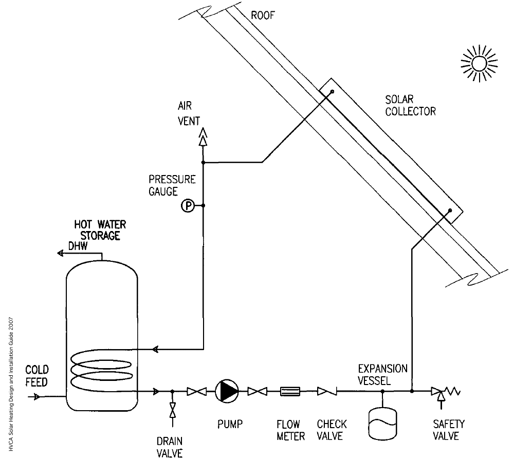
The typical components of an indirect solar thermal system are shown in the diagram below. This diagram and others in this article are simplified and do not show the full controls for efficiency and safety needs however it is essential to note that no means of isolation should be placed between the collector and the safety relief valve.
Image: A closed pumped system.
The water supplying the domestic hot water outlets is potable but the primary water from the solar collectors may be a glycol mix or non-potable water in indirect systems. NB for direct systems (that heat the domestic hot water directly in the collectors) it must be potable.
In many stores, to maximise the heat capacity, and to make water available for space heating, the water drawn off from the solar cylinder can be at a temperature that is too high to pass directly to hot water outlets. Some mixing arrangement, or a secondary, lower temperature will be used to ensure safe temperatures.
The design of the systems and their installation should specifically prevent the following:
- Scalding risk from steam or hot water. Failsafe control is required to keep temperatures safe at water outlets.
- Freezing of fluids where it might cause damage or block pipes and safety valves.
- Accumulation of solids or bacteria. Some water treatment may be needed, particularly in direct systems.
- Legionella bacteria developing within the consumed drinking or shower water. The system operation must meet the requirements of HSE Code of Practice L8 for the control of Legionella. This will normally mean a loss in overall seasonal efficiency as auxiliary heating will be required and must be maintained in use.
- Degrading of water quality due to contact with materials and fittings during stagnation. The oversizing of systems will make the chances of stagnation more likely.
- Backflow or thermo-siphoning of heated water into a cold water cistern.
- Disturbance of stratification in the solar storage vessel during normal operation. This will be disturbed in 'sterilisation' cycles.
- Loss of dedicated solar storage capacity. Systems that are designed to operate with storage will stagnate if they are run without the storage being available.
- Loss of liquid from the system through overflow. Any liquid that is lost has to be replaced. This will affect the composition of the anti-freeze additives and will also allow more oxygen and solids into the system. The expansion vessel should be large enough so that any stagnation does not cause fluid loss through the safety device. In closed systems a heat dump mechanism, typically a radiator, can be used to dissipate heat when the hot water store can accept no more.
Systems in the UK are likely to be either a fully-pumped or drain-back configuration. In climates where freezing is unlikely syphonic systems may be used but there application is unlikely in the UK.
[edit] Fully pumped systems
This is the dominant type of system that is used in residential property through to large commercial and industrial applications. They are generally designed so that the exposed components will not tolerate freezing liquids and so must circulate water including glycol antifreeze in a closed loop separated from the potable domestic hot water using a coil to exchange heat in the cylinder.
Image: A simple sealed solar thermal system.
Some systems are available using materials and pipework that can accept freezing water. These can use potable water in a direct system avoiding the need for a domestic hot water heat exchanger. Since the water is being continuously refreshed there may be some water treatment needed to prevent an accumulation of scale or solids.
Image: A direct solar system using potable water.
Temperature sensors compare the temperature in the collector and the store and if heat is available and needed the pump will switch on, typically when the bottom of the store is 6K - 10K cooler than the collector.
When heat is available, but the store is already at design temperature, there is a risk of stagnation. Some systems will have an additional circuit to reject this heat. Stagnation occurs when the solar system doesn't have anywhere to put the heat that is being collected from the sun. In such conditions flat plate systems can reach temperatures of over 170°C and evacuated tubes over 200°C. At these temperatures in indirect systems, the propylene glycol becomes more acidic and the effectiveness of the glycol to act as an antifreeze will degrade. Closed systems have to be designed to accommodate some boiling (and expansion) using an expansion vessel, or they will release fluid through the safety valve, which can be hazardous and cause a maintenance problem.
When it is expected that systems will be left unattended or unused during periods of high solar insolation appropriate provision for controlling the potentially damaging build-up of heat must be made.
The check valve prevents reverse gravity circulation cooling the water store. This could otherwise occur when the pump is not operating and the collector contains colder, more dense fluid as would be typical at night.
Any pumps in such systems are required by the Building Regulations to consume fewer than 50W, or less than 2% of the peak thermal power of collector, whichever is higher.
[edit] Drainback system
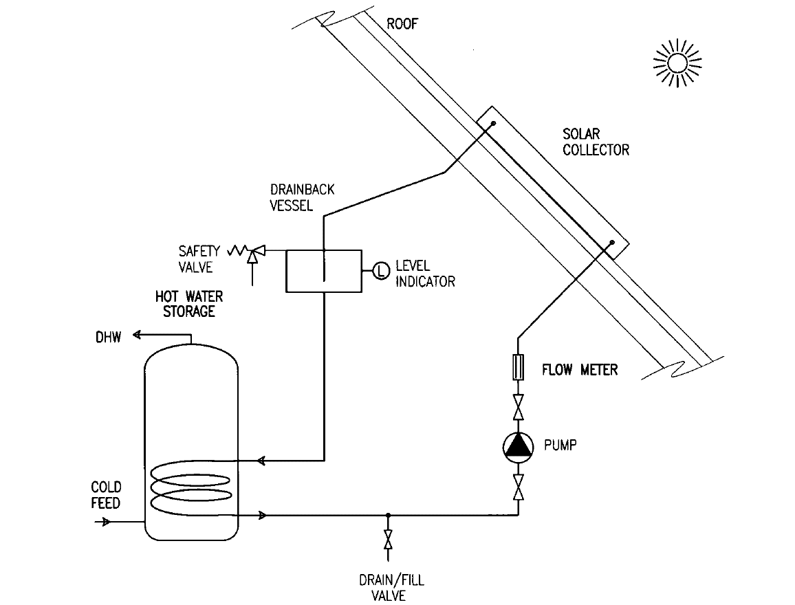
The drainback system uses a differential temperature pump controller to compare the temperature in the collector and the store. If heat is available and needed, the pump will switch on. The pump draws liquid from the bottom of the drainback vessel and pumps it up through the top of the solar collectors to return by gravity to the drainback vessel. When the system is not in use or when there is no call for heat, the pump switches off and the water drains from the collectors into the drainback vessel.
Image: A simple drainback system.
Draining back prevents unwanted reverse circulation and overheating and risks from stagnation but is practically limited to residential-sized applications.
The claimed benefits of a drain back system are:
- Gravity is fail-proof and maintenance free.
- Water (or a glycol mixture) may be used in the collector loop.
- The system is not damaged if the pump fails.
- The system cannot reverse thermosyphon at night.
- Collector plates are likely to last longer than in a pressurized glycol system.
However there are also disadvantages:
- Collectors and piping must be above and slope downwards towards the reservoir.
- Larger piping and insulation must be used.
- There are relatively large pumping requirements, especially if the design involves multistory buildings.
- System and pump controls cost approximately 10% of the solar savings (photovoltaic powered pumps are not strong enough).
- Components cost about 10-15% more than a glycol system.
- Systems can be noisy.
[edit] Thermal stores and combi-systems
A thermal store will be needed to make solar heating practical. For small residential applications this frequently shares the function of the hot water cylinder. With indirect systems a second coil will be in the lower part of the cylinder to exchange the heat from the solar collectors into the potable domestic hot water.
Image: Section through a purpose made solar thermal store.
Larger non-domestic applications will commonly use an additional storage vessel that will act as a preheated feed to the traditional hot water heating system. In the case of a swimming pool installation, the pool itself acts as the thermal store.
Purpose designed thermal stores are becoming increasingly common where the heat from solar panels is used to indirectly preheat water in the store that is then heated directly by the auxiliary heating device (eg a gas boiler).
This water then provides the (non-potable) primary heating water and a coil is immersed in the cylinder to instantaneously provide heat for domestic hot water. These systems are known as 'combisystems'.
The sizing of the store is as critical as the collectors in ensuring that the maximum benefit is gained from the system. As solar systems become more commonly used, dedicated solar stores (separate from the potable hot water system) are being used in the UK. The size of the associated solar storage tank will depend on the type and frequency of hot water use in the building. Its role is to provide a store for solar heat that is not immediately used by the building. Information from Germany suggests that storage of approximately 50 litres is required per sq m collector area for large-scale installations with reasonably constant weekday use and 60-70 litres per sq m collector area for those where there are consumption free weekdays.
[edit] Factors to consider prior to installation
There is a comprehensive list of factors that should be considered prior to installation in the Energy Savings Trust's Solar water heating systems – guidance for professionals, conventional indirect models. These include:
- Occupant’s domestic how water usage pattern.
- Shading. The seasonal influence of trees and local buildings.
- Collector fixing slope and orientation. The limitations of the particular roof, wall or ground fixing.
- Collector fixing area, structure and covering. The methods that may be used to fix the collector.
- Access to collector location, ensuring safe access for installation and servicing.
- Domestic hot water heat sources. To confirm that auxiliary heating is able to coexist and work in conjunction with solar thermal.
- Pre-heat storage locations. Ensure that there is the opportunity to integrate appropriate pre-heat facilities (if required).
- Secondary water pressure and quality.
This article has been reproduced here with the kind permission of the Building & Engineering Services Association. The original article, along with other resources, can be seen on their website: www.b-es.org
[edit] Related articles on Designing Buildings
- BRE National Solar Centre.
- Coefficient of Performance CoP.
- Flexible Solar Panels.
- Geothermal pile foundations.
- Green Deal.
- Large scale solar thermal energy.
- Microgeneration Certification Scheme 2020.
- Odeillo solar furnace.
- Renewable energy sources: how they work and what they deliver: Part 4: Solar thermal hot water systems DG 532 4.
- Solar-assisted heat pump.
- Solar photovoltaics.
- Wind loads on roof-mounted photovoltaic and solar thermal systems DG 489.
[edit] External references
- BRE National Solar Centre.
- B&ES's 'Solar Heating Design and Installation Guide'.
- CIBSE Knowledge Series 15 – 'Capturing solar energy'.
- The B&ES document - SMG 2000 - Standard Maintenance Specification for Services in Buildings provides advice on the maintenance needs of such systems.
- ASHRAE Systems Handbook 2008, Chapter 36.
- ASHRAE Applications Handbook 2007 – Chapter 33: Solar Energy Use.
- Solar Thermal Systems - Successful Planning and Construction' - Felix Peuser et al.
- US Department of Energy resource - Active Solar Heating.
- Natural Resources Canada.
- RETScreen to determine the benefits of using solar thermal in different locations.
- US based Whole Building Design Guide provides detailed descriptions on solar thermal technologies
- Energy Savings Trust, Solar water heating systems – guidance for professionals, conventional indirect models (2006 edition).
- ASHRAE Solar Heating Guidelines.
- Energy Technology List Solar thermal technology - A guide to equipment eligible for Enhanced Capital Allowances.
- Solar Water Heating - A Buyer’s Guide
- Microgeneration Installation Standard:MIS3001,Requirements for Contractors Undertaking The Supply, Design, Installation, Set to Work Commissioning and Handover of Solar Heating Microgeneration Systems Issue 2.0 DECC 2009.
- BS5918:1989 Code of practice for solar heating systems for domestic hot water.
- BS EN 12975:2006 Thermal solar systems and components.
- Legionnaires' disease. The control of legionella bacteria in water systems.
- DCLG Domestic Building Services Compliance Guide 2010 Edition includes requirements for collector installations up to 20 sq m and solar heated water storage of less than 440 litres (but only indirect systems).
Featured articles and news
Homes England creates largest housing-led site in the North
Successful, 34 hectare land acquisition with the residential allocation now completed.
Scottish apprenticeship training proposals
General support although better accountability and transparency is sought.
The history of building regulations
A story of belated action in response to crisis.
Moisture, fire safety and emerging trends in living walls
How wet is your wall?
Current policy explained and newly published consultation by the UK and Welsh Governments.
British architecture 1919–39. Book review.
Conservation of listed prefabs in Moseley.
Energy industry calls for urgent reform.
Heritage staff wellbeing at work survey.
A five minute introduction.
50th Golden anniversary ECA Edmundson apprentice award
Showcasing the very best electrotechnical and engineering services for half a century.
Welsh government consults on HRBs and reg changes
Seeking feedback on a new regulatory regime and a broad range of issues.
CIOB Client Guide (2nd edition) March 2025
Free download covering statutory dutyholder roles under the Building Safety Act and much more.
Minister quizzed, as responsibility transfers to MHCLG and BSR publishes new building control guidance.
UK environmental regulations reform 2025
Amid wider new approaches to ensure regulators and regulation support growth.
BSRIA Statutory Compliance Inspection Checklist
BG80/2025 now significantly updated to include requirements related to important changes in legislation.

















Comments
The first point to make is you have to stop using the term 'combi- systems' it is a term used to describe a type of boiler and has nothing in common with solar thermal systems. The continent may well use that term, but it will simply cause confusion in the UK.
It would appear that the UK has at last decided to allow engineers to get on with designing and fitting solar thermal space heating systems (well not quite yet, but soon) The time wasted while the carbon dioxide output rises is amazing.
I have a number of full systems in operation with excellent results all round-it isn't rocket science despite what some sections of the technical community say. My view is that solar thermal space heating has been suppressed in the UK so that someone can get some sort of control over it. For years I have read the absolute twaddle put to us by the so called experts, and wondered how my designs have worked so well.
It is a very simple concept:- design the heat emitter circuit, preferably floor heating, calculate the amount of storage required to provide a sensible step between supply and demand, then calculate the amount of panels to manage that. ALWAYS REMEMBERING THAT IF A PANEL SYSTEM IS STAGNATING IT IS A SURE SIGN OF INSUFFICIENT STORAGE.
Douglas Haigh Fellow institute donestic heating and environmental engineers. 22/11/2018