Types of drawings for building design
[edit] Why are drawings used for building design?
Drawings are a graphical way of representing something in two-dimensions. They are commonly used as a way of developing and communicating designs for buildings and other built assets, and range from early concept sketches through to instructions for contractors and as-built records of completed buildings. Typically, drawings will begin as rough outlines and zoning diagrams and will progress through to very detailed, scaled drawings.
[edit] How are drawings prepared?
Traditionally, drawings were prepared on paper, but increasingly, they are being developed digitally, using computer aided design (CAD), or building information modelling (BIM) software.
For more information see:
[edit] Who prepares design drawings?
Drawings may be prepared by designers such as architects and engineers, or by contractors, subcontractors, manufacturers and other suppliers. They may also be outsourced to third party organisations that specialise in preparing or completing drawings.
For more information see: Designers.
[edit] Types of drawings
Many different types of drawing can be used during the process of designing and constructing buildings. Some of the more commonly-used types of drawing are listed below, with links to articles providing further information.
See also: Video overview of different types of drawings.
[edit] As-built drawings and record drawings
On building projects, it is common for changes to be made during construction because of circumstances that emerge on site. As a result, it is common for as-built drawings to be prepared, either during the construction process or when construction is complete, to reflect what has actually been built.
The contractor will generally mark up changes to the ‘final construction issue’ drawings on-site using red ink, and these can then be used by the consultant team to create record drawings showing the completed project.
For more information see: As-built drawings and record drawings.
See also: As-installed drawing.
[edit] Assembly drawings
Assembly drawings can be used to represent items that consist of more than one component. They show how the components fit together and may include, orthogonal plans, sections and elevations, or three-dimensional views, showing the assembled components, or an exploded view showing the relationship between the components and how they fit together.
For more information see: Assembly drawing and Exploded view.
[edit] Block plan
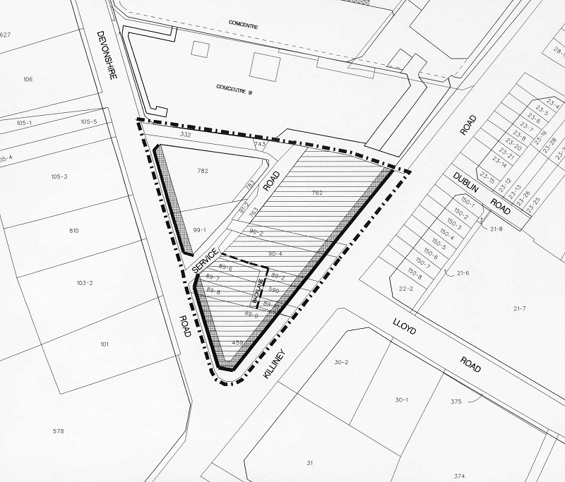
Block plans usually show the siting of a project in relation to Ordnance Survey Maps. Conventions are used to depict boundaries, roads and other details. Depending on the size of the project, recommended scales are:
- 1 : 2500
- 1 : 1250
- 1 : 500
For more information, see Block plan.
[edit] Component drawings
Generally, components are ‘self-contained’ and sourced from a single supplier, typically the complete unit provided by that supplier rather than its constituent parts. Component drawings provide detailed information about the individual units. They may be drawn at large scales such as; 1:10, 1:5, 1:2, 1:1, and so on. They may include information such as component dimensions, construction, tolerances, and so on.
For more information see: Component drawing.
[edit] Concept drawings and sketches
Concept drawings or sketches are drawings, often freehand, that are used as a quick and simple way of exploring initial ideas for designs. They are not intended to be accurate or definitive, merely a way of investigating and communicating design principles and aesthetic concepts.
For more information see: Concept drawing.
[edit] Construction drawings and working drawings
Working drawings or construction drawings provide dimensioned, graphical information that can be used; by a contractor to construct the works, or by suppliers to fabricate components of the works or to assemble or install components. Along with specifications and bills of quantities or schedules of work, they form a part of the 'production information', that is prepared by designers and passed to the construction team to enable a project to be constructed.
For more information see: Construction drawing and working drawing
[edit] Design drawings
Design drawings are used to develop and communicate ideas about a developing design. In the early stages they might simply demonstrate to the client the ability of a particular design team to undertake the design. They may then be used to develop and communicate the brief, investigate potential sites and assess options, develop the approved idea into a coherent and co-ordinated design, and so on.
For more information see: Design drawings.
[edit] Detail drawings
Detail drawings provide a detailed description of the geometric form of a part of an object such as a building, bridge, tunnel, machine, plant, and so on. They tend to be large-scale drawings that show in detail parts that may be included in less detail on general arrangement drawings.
For more information see: Detail drawing.
[edit] Electrical drawing
An electrical drawing, also known as a wiring diagram, is a type of technical drawing that provides visual representation and information relating to an electrical system or circuit. They are used to convey the engineering design to the electricians or other workers who will use them to help instal the electrical system.
For more information, see Electrical drawing.
[edit] Elevations
The term ‘elevation’ refers to an orthographic projection of the exterior (or sometimes the interior) faces of a building, that is a two-dimensional drawing of the building’s façades. As buildings are rarely simple rectangular shapes in plan, an elevation drawing is a first angle projection that shows all parts of the building as seen from a particular direction with the perspective flattened. Generally, elevations are produced for four directional views, for example, north, south, east, west.
For more information see: Elevations.
[edit] Floor plans
Floor plans are a form of orthographic projection that can be used to show the layout of rooms within buildings, as seen from above. They may be prepared as part of the design process, or to provide instructions for construction, often associated with other drawings, schedules, and specifications.
For more information see: Floor plan.
[edit] Engineering drawing
An engineering drawing is a type of technical drawing used to define the requirements for engineering products or components. Typically, the purpose of an engineering drawing is to clearly and accurately capture all geometric features of a product or component so that a manufacturer or engineer can produce the required item.
For more information see: Engineering drawing.
[edit] Location drawings/general arrangement drawings
General arrangement drawings (GA’s, sometimes referred to as location drawings) present the overall composition of an object such as a building. Depending on the complexity of the building, this is likely to require a number of different projections, such as plans, sections and elevations, and may be spread across several different drawings.
For more information see: General arrangement drawing.
[edit] Installation drawings
Installation drawings present the information needed by trades to install part of the works. This may be particularly important for complex installations such as plant rooms, data centres, ventilation systems, underfloor heating, and so on.
For more information see: Installation drawing.
[edit] Location plan
A location plan is a supporting document that may be required by a planning authority as part of a planning application. A location plan provides an illustration of the proposed development in its surrounding context.
For more information, see Location plan.
[edit] Perspective
Perspective drawing is a technique for depicting three-dimensional volumes and spatial relationships based on the eye level and vanishing point (or points) of the viewer. It can give a realistic impression of what a volume or space will look like in reality.
Constructing perspective drawings of buildings is extremely complicated, but has been much simplified recently by the development of computer aided design (CAD), building information modelling (BIM) and other forms of computer generated imagery (CGI).
To find out more about perspective, see: The origins of perspective.
[edit] Production drawing
Production drawings illustrate how to manufacture a product, providing information about dimensions, materials, finishes, tools required, methods of assembly and so on. They are used as instructional reference documents by workers and their supervisors on the shop floor or production line to manufacture the products required.
For more information see: Production drawing.
[edit] Scale drawing
Scale drawing is a generic term used to describe any drawing that illustrates items at less than (or more than) their actual size. This is generally necessary where the items is so large or small that it is not useful or convenient to draw it at its actual size.
For more information see: Scale drawing.
[edit] Section drawings
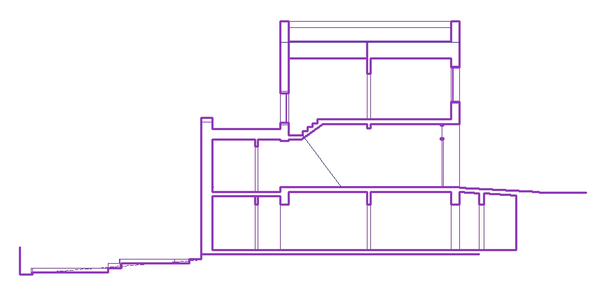
A section drawing shows a view of a structure as though it had been sliced in half or cut along another imaginary plane. This can be useful as it gives a view through the spaces and surrounding structures (typically across a vertical plane) that can reveal the relationships between the different parts of the buildings that might not be apparent on plan drawings.
For more information see: Section drawings.
[edit] Shop drawings
Shop drawings might be prepared by contractors, subcontractors, suppliers, manufacturers or fabricators. They generally relate to pre-fabricated components, showing how they should be manufactured or installed. They take design intent drawings and specifications prepared by the project design team and develop them to show in detail how the component will actually be manufactured, fabricated, assembled or installed.
For more information see: Shop drawing
[edit] Site plans
A site plan is a large-scale drawing that shows the full extent of the site for an existing or proposed development. Site plans, along with location plans, may be necessary for planning applications. In most cases, site plans will be drawn up following a series of desk studies and site investigations.
For more information see: Site plan.
[edit] Technical drawings
The term ‘technical drawing’ has a very broad meaning, referring to any drawing that conveys the way that something functions or how it is constructed. Technical drawings are intended to convey one specific meaning, as opposed to artistic drawings which are expressive and may be interpreted in a number of ways. Most drawings prepared during the design and construction of buildings might be considered to be technical drawings.
For more information see: Technical drawing.
[edit] Other types of drawing
[edit] Other meanings of the word 'drawing'
The word 'drawing' can also refer to: 'Mechanised methods of extracting a cylinder or, more commonly, a sheet of glass from a melt. Sheets were drawn from tank furnaces using equipment that gripped a layer of glass as it started to solidify.' Ref Archaeological Evidence for Glassworking, Guidelines for Recovering, Analysing and Interpreting Evidence, published by Historic England in 2018.
[edit] Related articles on Designing Buildings
- As-built drawings and record drawings.
- As-installed drawing.
- Component drawing.
- Concept drawing.
- Construction drawing.
- Design drawings.
- Detail drawing.
- Diagram.
- Drawing board.
- Elevations.
- Engineering drawing.
- Floor plan.
- General arrangement drawing.
- Production drawing.
- Scale drawing.
- Section drawing.
- Shop drawings.
- Site layout plan.
- Site plan.
- Symbols on architectural drawings.
- Technical drawing.
- Title plan.
- Types of building models.
- Types of paper.
- Types of projection.
- Visualisation.
- Working drawing.
Featured articles and news
OpenUSD possibilities: Look before you leap
Being ready for the OpenUSD solutions set to transform architecture and design.
Global Asbestos Awareness Week 2025
Highlighting the continuing threat to trades persons.
Retrofit of Buildings, a CIOB Technical Publication
Now available in Arabic and Chinese aswell as English.
The context, schemes, standards, roles and relevance of the Building Safety Act.
Retrofit 25 – What's Stopping Us?
Exhibition Opens at The Building Centre.
Types of work to existing buildings
A simple circular economy wiki breakdown with further links.
A threat to the creativity that makes London special.
How can digital twins boost profitability within construction?
The smart construction dashboard, as-built data and site changes forming an accurate digital twin.
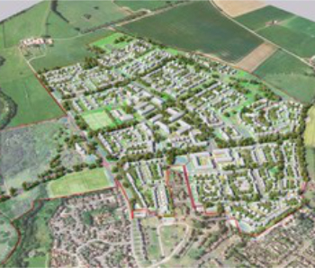
Unlocking surplus public defence land and more to speed up the delivery of housing.
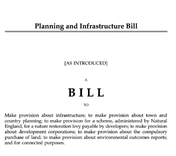
The Planning and Infrastructure Bill
An outline of the bill with a mix of reactions on potential impacts from IHBC, CIEEM, CIC, ACE and EIC.
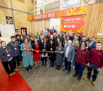
Farnborough College Unveils its Half-house for Sustainable Construction Training.
Spring Statement 2025 with reactions from industry
Confirming previously announced funding, and welfare changes amid adjusted growth forecast.
Scottish Government responds to Grenfell report
As fund for unsafe cladding assessments is launched.
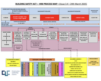
CLC and BSR process map for HRB approvals
One of the initial outputs of their weekly BSR meetings.
Building Safety Levy technical consultation response
Details of the planned levy now due in 2026.
Great British Energy install solar on school and NHS sites
200 schools and 200 NHS sites to get solar systems, as first project of the newly formed government initiative.
600 million for 60,000 more skilled construction workers
Announced by Treasury ahead of the Spring Statement.

















Comments
[edit] To make a comment about this article, click 'Add a comment' above. Separate your comments from any existing comments by inserting a horizontal line.
Really helpful to see so many different types of drawing described.