


Installation drawings

Installation drawings are developed from co-ordinated detail drawings and present the information needed by trades to install part of the works. This may be particularly important for complex installations such as plant rooms, data centres, ventilation systems, underfloor heating, and so on.
They may be prepared by the consultant team, or may be prepared by contractors, sub-contractors or suppliers and submitted for approval.
They may comprise plans, sections and elevations, but increasingly building information modelling (BIM) is being used to create detailed 3 dimensional representations of buildings and their components which may include installation information.
Installation drawings may include information about:
- Precise positioning.
- Supports and fixings.
- Information from manufacturers shop drawings.
- Space allowances for installation.
- Builders work in connection, such as; cutting and sealing holes, chasing block and brickwork for conduits or pipes, lifting and replacing floors, constructing plinths and so on.
- Plant or equipment requirements.
- Requirements for service connections.
- Requirement to leave access space for operation and maintenance.
- Other maintenance access requirements such as access panels, decking, platforms, ladders and handrails.
It is important that the information presented is carefully co-ordinated so that clashes are avoided.
Installation drawings may include specification information, or this may be provided in a separate specification, but information should not be duplicated as this can become contradictory and may cause confusion.
Design Framework for Building Services 5th Edition (BG 6/2018), written by David Churcher, John Sands & Martin Ronceray, and published by BSRIA in June 2018 suggests that installation drawings are:
|
Drawings based on the Technical Design drawings or coordinated working drawings with the primary purpose of defining that information needed by the tradesmen on site to install the works. The main features of installation drawings should be as per coordinated working drawings, plus:
|
[edit] Related articles on Designing Buildings Wiki
- As-built drawings and record drawings.
- Assembly drawing.
- Concept drawing.
- Design drawings.
- Detail drawing.
- Elevations.
- Engineering drawing.
- General arrangement drawing.
- Projections.
- Scale drawing.
- Section drawing.
- Shop drawing.
- Technical drawing.
- Types of drawing.
- Working drawing.
- Component drawings
Featured articles and news
Costs and insolvencies mount for SMEs, despite growth

Construction sector under insolvency and wage bill pressure in part linked to National Insurance, says report.
The place for vitrified clay pipes in modern infrastructure
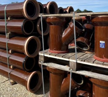
Why vitrified clay pipes are reclaiming their role in built projects.

Research by construction PR consultancy LMC published.
Roles and responsibilities of domestic clients

ACA Safety in Construction guide for domestic clients.
Fire door compliance in UK commercial buildings
![]()
Architect and manufacturer gives their low down.
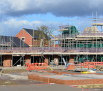
Plumbing and heating for sustainability in new properties

Technical Engineer runs through changes in regulations, innovations in materials, and product systems.
Awareness of the Carbon Border Adjustment Mechanism
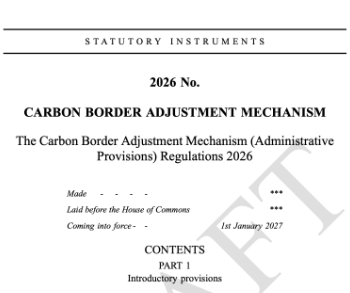
What CBAM is and what to do about it.
The new towns and strategic environmental assessments
12 locations of the New Towns Taskforce reduced to 7 within the new towns draft programme and open consultation.
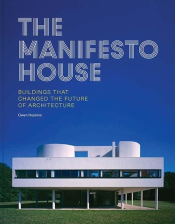
Buildings that changed the future of architecture. Book review.
The Sustainability Pathfinder© Handbook
Built environment agency launches free Pathfinder© tool to help businesses progress sustainability strategies.

Government outcome to the late payment consultation, ECA reacts.
IHBC 2025 Gus Astley Student Award winners
![]()
Work on the role of hewing in UK historic conservation a win for Jack Parker of Oxford Brookes University.
Future Homes Building Standards and plug-in solar
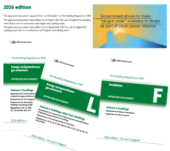
Parts F and L amendments, the availability of solar panels and industry responses.
How later living housing can help solve the housing crisis

Unlocking homes, unlocking lives.
Preparing safety case reports for HRBs under the BSA
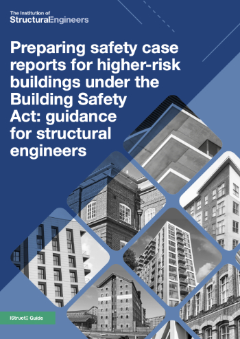
A new practical guide to preparing structural inputs for safety cases and safety case reports published by IStructE.
Male construction workers and prostate cancer

CIOB and Prostate Cancer UK encourage awareness of prostate cancer risks, and what to do about it.