


Scale drawing

|

|
Contents |
[edit] What are scale drawings?
Scale drawings are drawings that represent something at a size other than their full size. They can represent things at either a larger or a smaller scale than full size, depending on the size of the thing they are representing and the use to which the drawing will be put. The scale describes the ratio between a distance at full size, and the distance at the scale used that would be the same length.
[edit] What are scale drawings used for?
Scale drawings are used to illustrate items that it is not useful or convenient to draw at their actual size. This may be because drawing the item at full size would be unmanageable, or would not easily fit on a single sheet of paper (such as a building), or alternatively because items need to be drawn larger than full size to adequately represent all the detail that needs to be communicated (such as a complex connection).
The scale of drawings is described as a ratio using the notation:
| A distance at full size : The distance at the scale used that would be the same length. |
For example:
- A full size drawing would be 1:1 (or sometimes 1/1 or ‘one to one’).
- A half size drawing would be 1:2.
- A tenth size drawing would be 1:10.
- A double size drawing would be 2:1.
[edit] What are the most commonly used scales for drawings?
In the construction industry a range of scales are generally used depending on the nature of the drawing. For example:
- A location plan at 1:1000.
- A site plan at 1:200.
- A floor plan at 1:100.
- A room plan at 1:50.
- A component drawing at 1:5.
- An assembly drawing at 1:2.
[edit] How should scales be used on drawings?
It is important that the scale used is noted on the drawing. In addition, because of the ease of reproducing, printing and re-sizing drawings, it is important to note the original sheet size that the scale was drawn at, so for example A4, A3, A2, A1, A0, and so on.
See Paper sizes and Technical drawing pen sizes for more information.
Where a single sheet includes a range of drawings with different scales, these should all be noted.
In some cases, it may be appropriate to use more than one scale on a single drawing, for example, to show the elevation of land across across a significant distance. In this case, differences in elevation might be illustrated at a larger scale and a smaller scale used for horizontal distances. Here, the scale might be noted on the axes of the drawing, or actual distances shown on the axes.
In other cases a scale might use more than one unit of measurement. For example, the length of an arrow on an air flow diagram might represent the velocity of the air, e.g. 1 cm = 0.1 m/s.
The use of computer aided drawing (CAD) and building information modelling (BIM) has introduced a new concept to this process, as in this case, digital models are effectively created at full size. Drawings of any scale can then be generated from the model.
[edit] Related articles on Designing Buildings
- As-built drawings and record drawings.
- Assembly drawing.
- Blueprint.
- Building information modelling.
- Component drawing.
- Computer aided design.
- Concept drawing.
- Design drawings.
- Detail drawing.
- Drawing board.
- Elevations.
- Engineering drawing.
- General arrangement drawing.
- Installation drawings.
- Manual drafting techniques.
- North American Paper Sizes
- Notation and symbols.
- Paper sizes (ISO 216 A, B and C series).
- Perspective.
- Projections.
- Scale.
- Scale rule.
- Schematic.
- Section drawing.
- Shop drawings.
- Site plan.
- Symbols on architectural drawings.
- Technical drawing.
- Technical drawing pen sizes.
- Techniques for drawing buildings.
- Types of drawing.
- Working drawing.
Featured articles and news
Costs and insolvencies mount for SMEs, despite growth

Construction sector under insolvency and wage bill pressure in part linked to National Insurance, says report.
The place for vitrified clay pipes in modern infrastructure
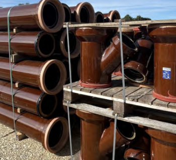
Why vitrified clay pipes are reclaiming their role in built projects.

Research by construction PR consultancy LMC published.
Roles and responsibilities of domestic clients
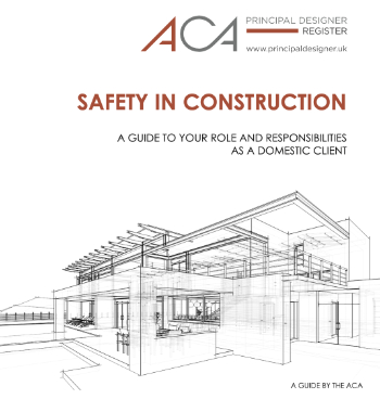
ACA Safety in Construction guide for domestic clients.
Fire door compliance in UK commercial buildings
![]()
Architect and manufacturer gives their low down.
Plumbing and heating for sustainability in new properties

Technical Engineer runs through changes in regulations, innovations in materials, and product systems.
Awareness of the Carbon Border Adjustment Mechanism
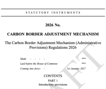
What CBAM is and what to do about it.
The new towns and strategic environmental assessments
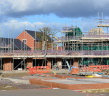
12 locations of the New Towns Taskforce reduced to 7 within the new towns draft programme and open consultation.
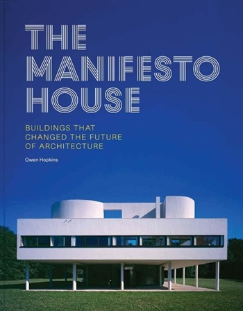
Buildings that changed the future of architecture. Book review.
The Sustainability Pathfinder© Handbook
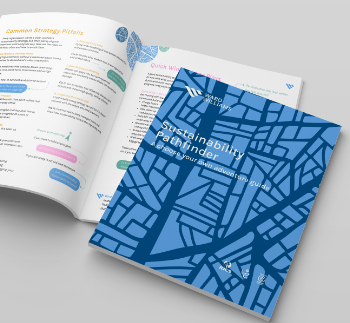
Built environment agency launches free Pathfinder© tool to help businesses progress sustainability strategies.

Government outcome to the late payment consultation, ECA reacts.
IHBC 2025 Gus Astley Student Award winners
![]()
Work on the role of hewing in UK historic conservation a win for Jack Parker of Oxford Brookes University.
Future Homes Building Standards and plug-in solar
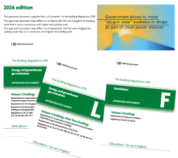
Parts F and L amendments, the availability of solar panels and industry responses.
How later living housing can help solve the housing crisis

Unlocking homes, unlocking lives.
Preparing safety case reports for HRBs under the BSA
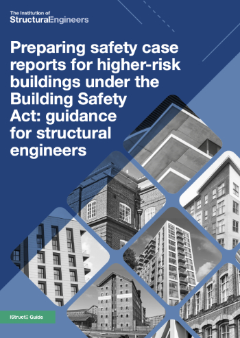
A new practical guide to preparing structural inputs for safety cases and safety case reports published by IStructE.
Male construction workers and prostate cancer

CIOB and Prostate Cancer UK encourage awareness of prostate cancer risks, and what to do about it.