CIBSE Case Study London Olympic Aquatics Centre
--CIBSE 15:14, 29 July 2014 (BST)
Article from the July 2012 edition of the CIBSE Journal written by Michael Stych and Howard But, Arup.
Contents |
[edit] Introduction
The London Aquatics Centre was in full Olympics mode during the 2012 Games. But the centre's innovative, eco-friendly building services design also provides a lasting energy-efficient facility for the nation. Like its neighbouring athletics stadium, the London Aquatics Centre was designed to provide a lasting Olympics legacy for the capital and the nation. The centre permanently accommodates 2,500 spectators, making it the largest swimming venue in the UK. During the Olympics the addition of two temporary, covered stands will provide a further 15,000 seats.
The Olympic Delivery Authority's energy strategy requires that the centre is able to demonstrate an overall 50% carbon emission reduction on current Building Regulations (2006 at the time). Like other venues on site, the centre has to be integrated into the Olympic Park's energy centre (see the article on the energy centre in the August 2011 Journal, page 16).
The large volume of the main pool hall, which measures 180,000 sq m, required a unique approach for controlling the indoor environment. A series of microclimates has been created within the hall to achieve the right comfort conditions while minimising energy consumption. This microclimate solution also uses temporary systems when the centre is expanded for the Olympic and Paralympics Games.
The building was initially constructed in Olympic Games mode to enable full testing and commissioning of the systems. A temporary screen was then installed to reduce the volume of the space, to minimise energy use while accommodating test events and training. Following the Games, the temporary stands will be removed and new façades installed to complete the legacy building.
The heating, cooling and ventilation systems are designed to accommodate these changes in operation, without compromising the permanent installations.
[edit] Ventilation
Early design options included the use of high velocity jet nozzles, a conventional approach to condition large venues. Modelling analysis showed that, while it was possible to achieve the temperatures required at poolside with this system, there was an inherent instability in the air flow patterns, which gave rise to draughts and ultimately discomfort. There was also risk of interference with other systems in the hall.
Thus, the chosen solution is a low velocity supply system at poolside level relying on natural convection within the hall. As the pool water surface absorbs heat, it draws supply air down, which is then extracted via the pool drainage channels along the pool edge. This also helps keep contaminated air at the pool surface and limits migration to other areas.
Four high-performance specialist air handing units (AHUs) supply conditioned air via the pool surround ventilation grilles, and air is extracted through air slots integrated within overflow water channels. The majority of air distribution is within services ducts on each side of the pool tanks. Services such as pool water pipework, the moveable floors and booms equipment are located within the ducts to allow accessibility for maintenance.
All four air handling units feature double-pass plate heat exchangers to achieve a heat recovery efficiency of up to 84%. The AHU control adjusts the fresh air ratio into the air system to control the space humidity level.
The low-velocity warm air supply louvres provide comfortable conditions in the pool surrounds, while the self-balanced, low-level air extraction service limits the build-up and spread of moisture and pollutants. As this is dedicated to the pool surround, the total air change over the pool hall volume is only approximately one air change per hour.
The air is supplied at the required space temperature, typically at 30C so buoyancy is reduced. Heating is provided by other systems.
[edit] Heating
The poolside area has underfloor heating. This provides comfort for the swimmers and radiant heat to offset the radiant losses to surrounding surfaces.
The system also provides a hidden function that, by warming the low velocity supply air, encourages upwards air flow, thereby reducing the risk of air recirculation by the pool surround air extraction.
[edit] Spectator environment
Spectators will typically require different comfort conditions to those at the warm poolside, and so are provided with separate ventilation that is only required when events are running.
A dedicated spectator ventilation system provides conditioned heated or cooled fresh air to underseat grilles for the 2,500 spectators in the seating areas. This system consists of perforated plate grilles at each seat location supplying slightly cooler air down to 26C at low velocity. Air is extracted at the top of the raked seating area.
At peak times (midsummer with full capacity spectators) fresh air cooling will be necessary to cool the supply air to 26C. Cooling energy is provided by two 390kW water-cooled ammonia chillers. Each of the two non-HFC (hydrofluorocarbon) chillers is connected to a pair of dry air coolers and is located on the south-end of the building, enclosed by a green wall system. The condensing water circuits are connected with the pool heating circuit for diverting waste heat for pool water heating, reducing the overall heating demand.
[edit] Façade heating
Heat loss from the façades is treated separately by the use of natural convectors fed from the heating hot water system. Along the perimeter there is a trench heater system to offset heat losses, and limit condensation build up. On the taller façade elements, the mullions and transoms have integrated hot water pipes embedded to reduce the risk of condensation and limit down draughts.
Each curtain wall is fed by a dedicated variable temperature circuit that is weather compensation control.
The façade itself is made up of 3m by 1.5m double-glazed panels giving an overall U-value including frames of 1.40 W/sq m K. The façade has a 'light' solar performance coating to limit summer time solar gain, although generally throughout the year passive solar gain on this facade plays a key role in reducing heat demand.
[edit] Daylighting
The façade will also enable year-round daylight in the pool hall. The two elevations provide a uniform light level across the hall, meaning that the electrical lighting can be switched off for most daylight hours.
To offer protection from water surface glare, the façade has a frit pattern whose intensity varies depending on the orientation of the glazing. The south overhang also provides shading on the south west elevation from the summer peaks solar gains.
[edit] The Roof
The main pool hall is enclosed by the two-way spanning steel roof, with steel trusses of up to 16 m in depth. There is also a ceiling on the lower surface of the roof trusses that gives a substantial roof void zone. The roof void is a warm space insulated with 200 mm of mineral wool insulation. This gives the roof a U-value of 0.20 W/sq m K. Options to reduce the heated volume of the hall were investigated but discarded. The conclusion was that the elimination of cold bridges and interface details was essential to prevent the risk of condensation and outside air infiltration at the joints.
The permanent roof is a warm roof construction created by insulated cladding on the top and acoustic-lined timber cladding facing the pool tank.
To ensure air movement in the roof space, there are a number of circulation fans located at the walkways; the fans operate on a cyclical basis, or when the roof void temperature falls below a set point. The roof itself has a total design heat loss of 70 kW, so the fans are also sized to offset this load and eliminate the risks of downdraughts to the pools below. The roof temperature and humidity is monitored by an array of sensors to control void temperature above dew point at all times.
[edit] Pool Hall Volume
The pool hall, including the roof void space, has a total volume of 180,000 m3. Fabric heat losses from surfaces account for 60% of the pool hall space heating demand. However, the main concern with regards to envelope heat losses was infiltration at the interfaces between roof element and facade.
Although movement joint at the top of the facade will seal the building. Even with a sealed building and minimal thermal bridging and interfaces, the design air infiltration will still account for 40% of the total envelope heat losses.
[edit] Energy Efficiency
An energy model was built early on in the design to assess in detail the building energy loads and to assist in understanding where the predominant loads were and which were less significant. The model evolved with the design and formed the basis of both the Part L carbon emission calculation (as required for Building Control and to demonstrate Olympics Delivery Authority efficiency targets) and of building energy modelling in use in accordance with the ODA requirement.
The Aquatics Centre improvement on Building Regulations Part L 2006 is 49%, based on the as-built commissioning data, but prior to the legacy installation (such as the building air permeability test). This is broken down into 16.5% from efficiency measures in building services systems and the remainder from the district heating and power systems.
The base thermal model was also used to prepare more detailed energy performance modelling calculations to assess the building more closely to its intended use, outside of building regulations requirements.
A carbon emission comparison with other UK 50 m swimming pool venues was carried out. This information is from the existing building's Display Energy Certificate results. Each venue differs in area and function, for example, many contain more dry area sports facilities, which will naturally reduce the energy demand.
[edit] Conclusion
From the work carried out on the building environmental design, it is evident that setting targets was critical to the success of sustainability on the project. It provided the whole team with a common objective and requirement. The energy performance is a significant part of achieving the BREEAM Excellent rating that the project received.
The project integrates with the Olympic Park's systems at a district scale to achieve the best solution both for the Park and for future-proofing the heating supply.
The involvement of building services engineers in the very early stages of the design, not only in systems selection but in the use of building physics, was the key to achieving the 16.5% savings in carbon using efficiency measures alone, before applying renewable energy sources.
[edit] Energy saving measures and further improvements
The target is indeed very challenging for the building design team, since a conventional energy efficient approach to swimming pools is to install CHP to power the building and utilise waste heat for pool heating. However, as the building is connected to the district heating network, new approaches are required to maximise the building's energy saving potential.
Measures that have been put in place include:
- 200mm insulated roof – 0.20 W/sqm K;
- Insulated pool tanks and basement;
- Double glazed argon filled curtain walling – 1.40W/sqm K;
- 5m3/h.m2 building air permeability at 50 Pa;
- Localised climatic control;
- Use of water based systems for building envelope heating;
- Pool as heat sink for heating systems and condenser water system;
- 84% sensible heat recovery in pool ventilation systems;
- Low velocity systems to achieve a volume averaged SFP of 1.6 W/(l/s);
- Passive solar gain of south-west façade to hall;
- Automatic day lighting control within the main pool hall;
- Natural ventilation in Olympics mode for spectators;
- and Variable speed pumping.
How could this be further improved in operation? The design has incorporated this series of measures that together provide a very efficient approach to energy savings.
From experience of other large pool facilities, pool energy consumption is also very dependent on how the building is operated. As the operator comes on board for the legacy, what more could be done and what could the operator do to further improve?
Measures that could be considered include:
- Controlling the pool filtration system closely on demand to reduce pump power;
- Closely monitoring and controlling the demand based ventilation systems;
- Raising the pool moveable floors as pool cover to reduce evaporation at night and when pools not in use;
- Reducing the pool water temperature from 30C to 28C for leisure use;
- Reducing the poolside air temperature accordingly to the lower ranges of the standards;
- Demand control outside air using CO2/pollutant sensors;
- Addition of heat recovery from shower and back wash water (propriety systems now generally available to allow this);
- and Further decarbonising the district heating in the long term.
[edit] Related articles on Designing Buildings Wiki
Featured articles and news
Spring Statement 2025 with reactions from industry
Confirming previously announced funding, and welfare changes amid adjusted growth forecast.
Scottish Government responds to Grenfell report
As fund for unsafe cladding assessments is launched.
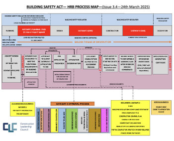
CLC and BSR process map for HRB approvals
One of the initial outputs of their weekly BSR meetings.
Architects Academy at an insulation manufacturing facility
Programme of technical engagement for aspiring designers.
Building Safety Levy technical consultation response
Details of the planned levy now due in 2026.
Great British Energy install solar on school and NHS sites
200 schools and 200 NHS sites to get solar systems, as first project of the newly formed government initiative.
600 million for 60,000 more skilled construction workers
Announced by Treasury ahead of the Spring Statement.
The restoration of the novelist’s birthplace in Eastwood.
Life Critical Fire Safety External Wall System LCFS EWS
Breaking down what is meant by this now often used term.
PAC report on the Remediation of Dangerous Cladding
Recommendations on workforce, transparency, support, insurance, funding, fraud and mismanagement.
New towns, expanded settlements and housing delivery
Modular inquiry asks if new towns and expanded settlements are an effective means of delivering housing.
Building Engineering Business Survey Q1 2025
Survey shows growth remains flat as skill shortages and volatile pricing persist.
Construction contract awards remain buoyant
Infrastructure up but residential struggles.
Warm Homes Plan and existing energy bill support policies
Breaking down what existing policies are and what they do.
A dynamic brand built for impact stitched into BSRIA’s building fabric.








Comments