


How to read technical drawings

Contents |
[edit] Introduction
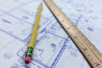
The term ‘technical drawing’ has a very broad meaning, referring to any drawing that conveys the way that something functions or how it is constructed. Most drawings prepared during the later stages of the design and construction of buildings might be considered to be technical drawings.
It is important that the purpose for which technical drawings are being prepared and the people that will use them are carefully considered to ensure they are properly structured and adopt an appropriate presentational techniques. It is also important to have an understanding of how to read them.
Some of the components common to many types of technical drawing are set out below.
[edit] Border
Most drawings have a border around them. This helps ensure that the full drawing is included in reproductions.
The border sometimes includes letters and numbers to delineate zones, in the same way as a map, to help locate and pinpoint certain areas. These letters are in alphabetical order from the bottom up on the vertical axis. The numbers are in numerical order from right to left on the horizontal access. The zones are to be read from right to left.
[edit] Title block
A title block will typically appear in the bottom-right corner of a drawing and contains information related to the drawing, including:
- Name: The company or agency that prepared the drawing.
- Address: Location of the company or agency.
- Names and dates: Individuals who drew, checked and approved the drawing, and the date they did so.
- Project: The project the drawing relates to.
- Description: What the drawing is of.
- Status: What the drawing is for (eg for construction / for information).
- Drawing number: The assigned number to identify the drawing.
- Revision: Identifies the correct version of the drawing, as it may have been revised several times.
- Scale: Ratio of actual size compared to the size on the drawing / or 'do not scale' if dimensions are not to be relied upon.
- Size: The original drawing sheet size (important for determining the scale for reproductions'. See paper sizes for more information.
[edit] Revision block
A separate revision block may be located in the top-right corner of the drawing, setting out:
- The number of the revision.
- The specific changes made compared to the previous drawings.
- The date that the revisions were made.
- The approval of the revision.
[edit] Scale
It is essential to understand the size scale that the drawing has been produced to. Actual size is 1:1. Where the scale is 100:1, it means that the actual size is 100 times that shown on the drawing; the first number represents the size of the physical element, and the second number represents the drawing. It is usual that the scale will be provided in the title block.
If the dimensions of elements on the drawing are not to be relied upon, for example if the drawing is a sketch, or if responsibility for determining dimensions are with another party, the scale may be followed by the statement 'do not scale' or 'not to scale'.
[edit] Basic symbols
Architectural symbols are often used to identify common features such as topography, brickwork, doors, windows, fixtures and other elements. Understanding these, or having access to a key which notates them, will be useful in terms of interpreting the drawing.
For more information, see Symbols on architectural drawings.
[edit] Notation and units
The same notation conventions should be followed by all so that there is clear communication between different people and mistakes are avoided.
See Notation and units on drawings and documents for more information.
[edit] Circled numbers
The scale of drawings may be too small to recreate all the necessary detail. In this case, circled numbers can be added to certain parts of the drawings, which indicate that the section identified is shown in greater detail on another page.
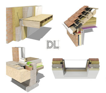
[edit] Projections and views
Drawings generally include front, side and top of views of the object being designed. These drawings are typically drawn in either parallel or perspective projections:
- Parallel projections include orthographic drawings in which the four orthogonal views of an object are shown.
- Perspective projections are drawings in which an object is drawn using one-, two- or three-point perspective; presenting the object as three-dimensional.
For more information, see Drawing projections.
Section views may also be included which show a structure as though it has been sliced in half or cut along another imaginary plane. For more information, see Section drawing.
Exploded views may also be shown, which show how an item is assembled. See Assembly drawing for more information.
[edit] Abbreviations
Similar to circled numbers, abbreviations are used to indicate elements and instructions. Some common abbreviations used in drawings include:
- & - and
- AFF - above finished floor
- BSMT - basement
- BYND - beyond
- BOT - bottom
- CLG - ceiling
- CONT - continuous
- CPT - carpet
- DBL - double
- DEMO - demolition
- DIA - diameter
- DIM - dimension
- DN - down
- DP - depth
- DR - door
- DWG - drawing
- EA - each
- EJ - expansion joint
- EL - elevation
- ELEC - electrical
- ELEV - elevator/elevation
- EXT - exterior
- FIXT - fixture
- FLR - floor
- FND - foundation
- GA - gauge
- HI - high
- HP - high point
- HVAC - heating, ventilating and air conditioning
- INSUL - insulation
- INT - interior
- LO - low
- MECH - mechanical
- MEMBR - membrane
- MTL - metal
- NO - number
- NOM - nominal
- OC - on centre
- PLUMB - plumbing
- PLYD - plywood
- PNT - paint/painted
- PVC - polyvinyl chloride
- REQD - required
- RM - room
- SIM - similar
- SPEC - specified
- STRUCT - structure
- TO - top of
- UNO - unless noted otherwise
- U/S - underside
- VIF - verify in field
- W/ - with
For more information see Acronyms.
[edit] Find out more
[edit] Related articles on Designing Buildings Wiki
- As-built drawings and record drawings.
- Assembly drawing.
- Component drawing.
- Computer aided design.
- Concept drawing.
- Detail drawing.
- Elevations.
- Engineering drawing.
- General arrangement drawing.
- How to take off construction works.
- Installation drawings.
- Notation and units on drawings and documents.
- Paper sizes.
- Production information.
- Projections.
- Section drawing.
- Symbols on architectural drawings.
- Types of drawing.
- Working drawing.
[edit] External references
- VistaIndustrial - How to read a drawing
Featured articles and news
Wellbeing in Buildings TG 10/2025

BSRIA topic guide updates.
![]()
With brief background and WELL v2™.
From studies, to books to a new project, with founder Emma Walshaw.
Types of drawings for building design
Still one of the most popular articles the A-Z of drawings.
Who, or What Does the Building Safety Act Apply To?
From compliance to competence in brief.

The remarkable story of a Highland architect.
Commissioning Responsibilities Framework BG 88/2025
BSRIA guidance on establishing clear roles and responsibilities for commissioning tasks.
An architectural movement to love or hate.
Don’t take British stone for granted

It won’t survive on supplying the heritage sector alone.
The Constructing Excellence Value Toolkit
![]()
Driving value-based decision making in construction.
Meet CIOB event in Northern Ireland

Inspiring the next generation of construction talent.
Reasons for using MVHR systems
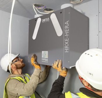
6 reasons for a whole-house approach to ventilation.
Supplementary Planning Documents, a reminder
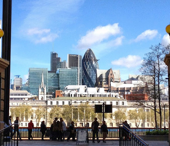
As used by the City of London to introduce a Retrofit first policy.
The what, how, why and when of deposit return schemes

Circular economy steps for plastic bottles and cans in England and Northern Ireland draws.
Join forces and share Building Safety knowledge in 2025

Why and how to contribute to the Building Safety Wiki.
Reporting on Payment Practices and Performance Regs

Approved amendment coming into effect 1 March 2025.