Sewer construction
[edit] Introduction
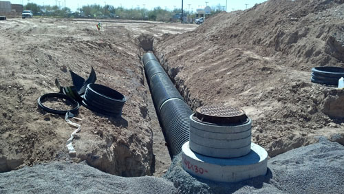
Sewers are expensive to construct and if not built correctly remedial works can be disruptive, time consuming, costly and, in some circumstances, have adverse effects on a company’s reputation. In many instances, a lot of mistakes can be avoided by considering the specification and requirements before and during construction. This is an on-site guide for contractors and operatives constructing sewers, with advice notes provided to avoid some of the common on site errors.
Sewers for Adoption (7th ed.) contains guidance for the design and construction of sewers that will be adopted by Sewerage Undertakers in England and Wales in accordance with Section 104 of the Water Industry Act 1991.
[edit] Safety in sewers and excavations
It is a contractor’s responsibility to ensure that all operatives are competent and experienced to complete works to the required standards.
[edit] Trenches and excavations
Trenches must be adequately supported, free from boulders and tree roots must be taken out. Muddy ground, water and soft areas in the trench base must be removed. Materials, spoil and equipment must be stored safely and plant should be operated within a safe working distance. The trench must be adequately protected from slips, trips, falls, site traffic, and have a safe means of access and egress.
Trenches should be adequately dewatered to provide a firm base but not dug wider than necessary as excessive loading may be placed on the pipe. Should ground conditions be unsuitable for pipe laying and manhole construction, an engineer must be consulted to design a solution.
[edit] Control of site and trench groundwater
In addition, care must be taken to prevent site debris, sludge or silt from entering the sewer network which could ultimately cause flow restrictions, blockages, flooding, pollution and also affect the receiving wastewater treatment works. Costs associated with such incidents may be recovered from those responsible. In addition, should an inappropriate discharge of site groundwater or construction material cause a pollution incident, this may lead to prosecution.
[edit] Agreed drawings
For sewer adoption and diversion works, construction must comply with the agreed drawings. Similarly, for public sewer connections, works must comply with the details which have been agreed by the Local Authority, the relevant Building Control Authority and the approval given by the contractor for the works to proceed. It is recommended that a site copy of the agreed drawings are available to those carrying out construction to avoid any mistakes or deviation from specification.
[edit] Construction materials
All materials including pipes must comply with the agreed drawings to Water Industry Standards (WIS) and be Kitemarked or have a similar EU certification mark.
All materials should be handled with care and stored safely in accordance with manufacture’s recommendations.
[edit] Manhole chambers
See also: Manhole.
[edit] Typical manhole chambers up to 3 m deep
Manholes should be constructed where there is a change of direction and/or a change of gradient, or where access is required for maintenance purposes. Such changes in direction or gradient must be made within the channel and not outside of the manhole or concealed by benching.
Manholes should also be positioned 0.5 m away from curb lines, preferably with the manhole cover positioned away from the wheel line of traffic.
[edit] Sizing of manhole chamber
Manhole bases should be sized to accommodate the main channel, lateral connection channels and provide a minimum 600 x 600 sq. mm landing area beneath the step rungs or ladder for main channels up to 375 mm. However, should there be several channels the size of the chamber may need to be increased.
N.B: Road cambers should be considered when positioning manholes with double covers across the centre of a carriageway.
[edit] Manhole base and channel construction
The manhole base should be a minimum of 225 mm deep to the barrel of the channel. To prevent the ingress of ground water and associated calcified deposits bleeding through the benching, the concrete should not be a dry mix and sufficiently compacted or pokered to remove voids and entrained air. Channels must be steep sided to at least the crown of the pipe.
[edit] Channels
The pipe joint adjacent to the channel should be a minimum of 100 mm from the internal face of the manhole. Lateral connections into the manhole must also enter the chamber as channels, again at 100 mm from the internal face of the chamber and connect to the main channel at soffit to soffit level, swept with the direction of main flow.
Minimum length of channel:
| Chamber diameter | ‘X’ min. |
| 1,200 | 950 |
| 1,500 | 1,050 |
| 1,800 | 1,150 |
| 2,100 | 1,300 |
| 2,400 | 1,450 |
| 2,700 | 1,550 |
| 3,000 | 1,700 |
[edit] Channel types
Channel inverts must be constructed using channel fittings for pipe diameters up to 300 mm. Clay and suitably fixed plastic channels are acceptable. Granolithic channels formed for smaller diameter channels often are either not sufficiently finished or the profile of the channel is not maintained, causing the accumulation of solids and associated odour complaints and as such are not acceptable.
Granolithic channels above 300 mm diameter must be finished with a steel float. Preformed plastic bases constructed within manhole rings are also not permitted. Preformed concrete and plastic coated concrete bases are permitted.
[edit] Lateral connection manhole channels
Lateral connections within manholes must meet the main channel at ‘soffit-to-soffit’ level with the channel commencing 100 mm from the chamber wall. All lateral channels must meet the main channel, swept in the direction of the main flow.
[edit] Manhole benching
Benching should be self-cleansing and formed with high strength concrete at a gradient of between 1:10-1:30. To maintain a smooth flow within the main channel, the benching must be formed vertically from the edge of the channel to at least the crown of the pipe.
[edit] Stub and rocker pipes
The manhole stub pipe must terminate within 150 mm from the external face of the manhole. The length of the rocker pipe used must correspond to the sewer diameter. For sewers up to 600 mm diameter, the rocker length must be 500-750 mm long.
NB: No rocker pipes are required on concrete pipes in excess of 1,050 mm diameter.
[edit] Setting out position of 1st ring and cover slab
The underside of the manhole ring must be situated between 50-300 mm above the crown of the pipe. The distance from finished ground level to the top step rung beneath the cover slab must not exceed 675 mm. A minimum distance of 150 mm between the underside of the cover slab to the top step iron must also be provided. It is recommended that the site engineer sets out the cover slab, concrete base and manhole ring levels to ensure that the above distances are provided.
[edit] Manhole rings and step irons
Manhole rings must be seated on a mortar bed and adequately pointed to prevent the ingress of ground water. Alternatively, proprietary bitumen or mastic bedding materials can be used. Manhole ring lifting eyes must be pointed flush with the chamber walls.
The step rungs must be plumb, in vertical alignment and equally spaced, leading to a landing area of a minimum area of 600 x 600 sq. mm from the edge of the main channel to the chamber wall.
[edit] Ladders
The distance from ground level to the 1st step or ladder rung must be no more than 675 mm. Remember the top step must be a minimum of 150 mm from the underside of the cover slab. A site engineer should set out the cover slab levels prior to construction so that this specification is achieved.
In areas of traffic loading, high ground water table levels or contaminated ground, 150 mm GEN 3 concrete surrounds to manhole chambers must be provided. Alternatively, wide wall rings can be considered.
Where the distance from ground level to the benching landing area is in excess of 3 m, step irons are not permitted and a ladder must be installed. Stainless steel or, in certain circumstances, glass reinforced plastic (GRP) ladders are acceptable.
[edit] Cover slabs and access openings
For 600 x 600 sq. mm openings on 1,050 mm diameter chamber rings and above, it is usual that a 600 x 750 mm cover slab is fitted, reduced to a 600 x 600 sq. mm opening by the use of an eccentric raising piece to suit the manhole cover and frame used.
Generally, where manhole chambers are between 1.5-3 m deep from finished ground level to benching landing area, a 600 x 600 mm clear unobstructed opening is normally suitable.
Where chambers are less than 1.5 m deep from finished ground level to benching landing area, consideration should be given to accessing and carrying out maintenance activities within the chamber.
For 1,050 mm and 1,200 mm diameter rings less than 1.5 m deep to benching, 750 x 750 mm covers shall be fitted.
For 1,500 mm diameter rings less than 1.5 m deep to benching, 1,200 x 675 mm covers shall be fitted.
NB: Cover slabs must not be cut to increase opening dimensions as this will significantly weaken the cover slab.
[edit] Positioning of cover slabs
Cover slabs must be positioned in square alignment with step irons or ladders and provide a minimum 600 x 600 sq. mm unobstructed opening. The internal face of the cover slab must be plumb with the outer edge of the step irons.
[edit] Adjusting brickwork, raising pieces and manhole cover and frames
1-3 courses of solid Class B engineering bricks should be used, free from thin masonry splits constructed using 3:1 cement sand mortar in English Bond.
NB: Normal house building mortar is unsuitable for constructing adjusting brickwork. Furthermore, masonry splits should only be used to achieve road cambers and gradients.
Alternatively, pre-cast raising pieces can be used, bedded on 3:1 sand/cement mortar or stronger. Proprietary shimming pieces should be used to achieve road cambers and gradients, etc.
NB: When calculating the number of masonry courses, the mortar bed beneath the manhole frame must not exceed 12 mm.
Both adjusting brickwork and raising pieces must be of sound construction, plumb, in alignment with the cover slab, free from holes, mortar snots with the mortar joints suitably pointed or flush with the brickwork. The rendering of adjusting brickwork or concrete seating rings is not permitted.
[edit] Manhole cover and frames
Sewers for Adoption specifies that all manhole frames located in adopted highways should be a minimum of 150 mm deep and only 100 mm frames are permitted in residential cul-de-sacs. Covers must be Kitemarked and comply with BS EN124 with Class D400 covers used in all areas used by road vehicles.
It is, however, recommended that all cover and frames subject to traffic loading have 150 mm deep cover and frames fitted.
Inappropriate bedding of manhole frames often leads to movement of both the manhole cover within the frame and the disintegration of the surrounding ground, especially in trafficked areas.
Before final surfacing, it is recommended that all frames are checked for alignment and sound bedding. Resetting frames and associated reinstatement can be costly, time consuming and spoil the appearance of a newly surfaced area.
Generally, covers must be bolted together with manhole key holes free from debris and ready for inspection.
[edit] Pipes and bedding
[edit] Sewer pipes and bedding specification
Pipes used on main adoptable sewer lengths must comply with Sewers for Adoption specification. Should there be any queries as to the suitability of materials, these should be clarified before construction.
Concrete pipes should comply with the requirements of BS EN 1916 and BS 5911-1.
Vitrified clay pipes should comply with requirements BS EN 295 for foul pipes and BS 65 for surface water pipes.
Thermoplastic structural walled pipes must comply with Water Industry Standard 4-35-01 and achieve Class 8k/Nm2 nominal short term ring stiffness.
Pipes must be Kitemarked or have a similar E.U. certification mark.
[edit] Handling and storage of pipes
Pipes are expensive and should be handled with care and stored safely in flat areas, away from excavations, stacked no greater than manufactures recommendations. In particular, PVC pipes should be stored on surfaces that prevent distortion of both the pipe circumference and linear profile.
[edit] Protection of sewers
Sewers located within highway or areas of traffic should have 1.2 m of cover. In other areas, 0.9 m of cover is required. Where this is not possible, a full protective concrete bed and surround must be provided, inclusive of flexible joints.
[edit] Pipe bedding
Pipes must be evenly bedded along the length of the pipe, usually full bed and surround for semi rigid and flexible pipe materials. Rigid pipes may require less granular bedding material e.g. Class B bedding (180 degrees bedding). The relevant standards (BS EN 1295-1, BS 9295, etc.), pipe manufacturer’s recommendations and agreed drawings should be consulted.
[edit] Laying and jointing of pipes
Pipes should be laid in 3 m maximum lengths with the joints ‘pushed home’ into sockets. Furthermore, care must be taken to ensure the pipe jointing seals are free from grit, silt etc. which will likely cause the pipe length to fail later air testing.
It is recommended that sewers are air tested at regular intervals as pipes are laid. Pipes should be cleanly cut, be free from defects and laid without back fall and dips.
It is recommended that sewers are laid using pipe lasers to achieve a single consistent gradient. Where there is little fall such as gradients up to 1:150 extra care should be taken to prevent dips. Back laying of pipes should be avoided where possible as level errors and the positioning of unforeseen existing services may require corrective measures which can be either expensive or impossible to rectify.
[edit] Backfilling
Pipes should be backfilled and compacted in 150 mm layers to 300 mm above the pipe crown. Care should be taken during compaction so that the sewer remains in good line and level, in particular adjacent to manhole chambers to prevent rocker pipes being pushed down from stub pipes.
[edit] Testing of sewers
Sewers up to 750 mm diameter must be available for testing either by air or water.
[edit] Air testing
For air testing, the sewer must hold a head from 100 mm to a minimum of 75 mm for 5 minutes once the pressure is initially stabilised.
[edit] Water testing
The sewer should be filled with water to provide 1.2-6 m head of water above the soffit of the pipes at the highest point. To allow for absorption, after 2 hours water should be added at 5 minute intervals and the volume of water required to keep the water at the initial level recorded. The rate of water loss must not exceed 0.5 litres / per 30 minutes / metre diameter / linear metre.
[edit] CCTV surveys
All sewers proposed for adoption must be inspected by CCTV survey. In advance of the CCTV survey, it is the developer’s responsibility to ensure that sewers are suitably cleansed otherwise the survey work will be abandoned.
Thermoplastic pipes are also subject to profile laser light-line surveying which measures any deformation within the pipeline. Pipes with deformation in excess of 5% must be replaced. For sewers subject to S185 Sewer Diversion Agreements, it is the developer’s responsibility to provide CCTV footage of cleansed sewers before flows are diverted. However, CCTV surveys recorded during the jetting works or surveys of dry pipelines are not suitable as an indication of the level of the pipe cannot be achieved.
NB: Pipe defects, dips, back fall and poor jointing highlighted by these surveys will need to be repaired.
[edit] Connections
[edit] Connections to existing public sewers
Depending on the number of properties that are served by the drain or sewer and the diameter of the main public sewer, connections can be made to:
- An existing public sewer manhole.
- A new manhole constructed on the public sewer.
- By the installation of a pre-formed oblique junction, matching the main sewer material, using proprietary couplings.
- By core-drilling the barrel of the pipe at 2 or 10 o’clock and installing a proprietary saddle fitting.
[edit] Connections to existing public sewer manholes
The dimensions and configuration of the existing public sewer manhole must be able to accommodate the new connection. Where this is not possible, a new manhole will need to be constructed. Connections must be made via a core drill so that the chamber remains in good order. Connecting pipe work should meet the main channel at ‘soffit to soffit’ level.
High level external back drop pipes must also be core drilled. Internal backdrop connections are generally not permitted. Channels should be used to turn the discharge to the direction with the main flow. Channels and high level pipes must not conflict with existing openings, step irons and must maintain a clear 600 x 600 mm clear landing area.
[edit] New manholes on existing public sewers
The diameter or size of a manhole chamber should provide sufficient access for maintenance such as jetting, CCTV surveys and man entry to the channels where required. A minimum 600 x 600 mm clear opening should be provided for manholes 1.5-3 m deep from benching to finished ground level.
New connection channels must not be constructed in the existing landing area. Connecting channels must be swept with the direction of main flow. The new connecting pipe work must meet the main channel at pipe ‘soffit to soffit level.
Channels must be from half barrel and not intrude into the main sewer flow. Where existing chambers do not provide sufficient space to make a new connection, chambers may have to be re-constructed with a larger chamber. ‘T’ Junctions should not be used.
[edit] Pre-formed junction connections
Oblique preformed junctions only must be installed using proprietary couplings. ‘T junctions must not be used.
Openings in the existing sewer must be squarely and accurately cut, free from rough edges. The installed fitting should be in good alignment with the existing sewer.
[edit] Core-drilled saddle connections
All saddle connections must be core-drilled. It should be noted that forming openings using circular cutting wheels weakens the pipe and causes structural defects.
Oblique saddle fittings must be used on pipes less than 450 mm diameter. Proprietary saddle fittings must be used on all connections. The internal saddle fitting diameter must not be greater than 1/3 of the main sewer internal diameter.
[edit] Back drop connections
Generally, internal backdrop connections are not permitted. Should an external backdrop have a high risk of blockages, a rodding point extending to ground level should be provided.
[edit] Access
[edit] Bespoke or manhole chambers for storage systems
Chamber ring diameters should be selected on size of manhole inlets and outlets and should also be able to accommodate the number of connections, associated channels and provide a minimum 600 mm x 600 mm landing area.
For 600 mm diameter pipes and above, where benching and a landing area is constructed 50% diameter above invert, a 500 mm x 150 mm recess must be cast within the manhole base, for step irons to be installed to lead down to the main channel invert.
[edit] Alternative access arrangements for larger diameter surface water sewer manholes
For 600 mm diameter surface water sewers and above with headroom limited to 2 m or less, suitable access into the channel can be achieved by a forming a recess within the manhole base, with step rungs installed leading down to a landing area formed and finishing at a point 150 mm above channel invert. Step rungs must be plumb and vertical alignment as shown below.
[edit] Fixings and rails
Safety chains are required on sewer outlets greater than 525 mm internal diameter. The chain must be 8 mm diameter and made from stainless steel.
Stainless steel and, in some circumstances, GRP handrails and balustrades are permitted.
This article was first published as 'Site Sewer Construction Guide' by United Utilities.
[edit] Related articles on Designing Buildings
- Approved Document H.
- Bund.
- Coastal defences.
- Culvert.
- Dam construction.
- Detention pond definition.
- Difference between drains and sewers.
- Dowsing.
- Drainage.
- Drainage stack.
- Groundwater control in urban areas.
- Highway drainage.
- Lateral drain.
- Manhole.
- Manhole cover.
- Private sewer.
- Public Health Act 1875.
- Public sewer.
- Reservoir construction.
- River engineering.
- Section 102 existing sewer adoption.
- Section 104 new sewer adoption.
- Safe working in drains and sewers.
- Sewerage.
- Soakaway.
- Soil vent pipe.
- Stink pipes.
- Sustainable urban drainage systems SUDS.
- Thames tideway tunnel.
- The redevelopment of Leicester's sewerage system by Joseph Gordon.
- Trenchless pipe rehabilitation market.
- Trenchless technology.
- Tunnelling.
- Water transfers and interconnections.
Featured articles and news
Moisture, fire safety and emerging trends in living walls
How wet is your wall?
Current policy explained and newly published consultation by the UK and Welsh Governments.
British architecture 1919–39. Book review.
Conservation of listed prefabs in Moseley.
Energy industry calls for urgent reform.
Heritage staff wellbeing at work survey.
A five minute introduction.
50th Golden anniversary ECA Edmundson apprentice award
Showcasing the very best electrotechnical and engineering services for half a century.
Welsh government consults on HRBs and reg changes
Seeking feedback on a new regulatory regime and a broad range of issues.
CIOB Client Guide (2nd edition) March 2025
Free download covering statutory dutyholder roles under the Building Safety Act and much more.
AI and automation in 3D modelling and spatial design
Can almost half of design development tasks be automated?
Minister quizzed, as responsibility transfers to MHCLG and BSR publishes new building control guidance.
UK environmental regulations reform 2025
Amid wider new approaches to ensure regulators and regulation support growth.
The maintenance challenge of tenements.
BSRIA Statutory Compliance Inspection Checklist
BG80/2025 now significantly updated to include requirements related to important changes in legislation.
Shortlist for the 2025 Roofscape Design Awards
Talent and innovation showcase announcement from the trussed rafter industry.










Comments