


Assembly drawing

Contents |
[edit] What are assembly drawings?
Assembly drawings are a type of technical drawing used to represent items that consist of more than one component. They show how those components fit together and may be in the form of, orthogonal plans, sections and elevations, or three-dimensional views.
The location of assemblies may be shown on general arrangement drawings, or sometimes on detail drawings. The components that form the assembly may be shown shop drawings that allow their fabrication.
[edit] What are assembly drawings for?
Assembly drawings may show assembled components, or an exploded view of the relationship between components and how they fit together. For example, they may be used to show how to assemble the parts of a kit such as furniture, how to assemble a complex part of a building (an assembly), or the relationship between a number of details.
[edit] What do assembly drawings include?
Assembly drawings might include instructions, lists of component parts, reference numbers, references to detail drawings or shop drawings, and specification information. They may also include dimensions, notation and symbols. It is important that these are consistent with industry standards so that their precise meaning is clear and can be understood.
Assembly drawings should not duplicate information provided elsewhere, as this can become contradictory and may cause confusion.
The scale at which drawings are prepared should reflect the level of detail of the information they are required to convey. Different line thicknesses can be used to provide greater clarity for certain elements.
Assembly drawings may be drawn to scale by hand, or prepared using Computer Aided Design (CAD) software. However, increasingly, building information modelling (BIM) is being used to create 3 dimensional representations of buildings and their components.
BS EN ISO 7519:1997 Technical drawings. Construction drawings. General principles of presentation for general arrangement and assembly drawings establishes general principles of presentation to be applied to construction drawings for general arrangement and assembly. This standard compliments the ISO 128 series on technical drawings.
[edit] What are the different types of assembly drawings?
Different types of assembly drawings include:
- General assembly drawings, showing an overall assembly.
- Outline assembly drawings, showing the exterior shape.
- Diagrammatic assembly drawings, representing the assembly with the use of symbols.
- Unit assembly or sub-assembly drawings, showing in more detail a part of the overall assembly.
- Fitted assembly drawings, showing the completed assembly.
- Exploded assembly drawing, showing the relationship between the separated parts.
[edit] Related articles on Designing Buildings
- As-built drawings and record drawings.
- Assembly.
- Building information modelling.
- Component drawing.
- Computer aided design.
- Design drawings.
- Detail drawing.
- Drawings.
- Engineering drawing.
- Exploded view.
- General arrangement drawing.
- Installation drawings.
- Notation and symbols.
- Production information.
- Projections.
- Scale drawing.
- Shop drawings.
- Technical drawing.
- Technical drawing pen sizes.
Featured articles and news
ECA progress on Welsh Recharging Electrical Skills Charter

Working hard to make progress on the ‘asks’ of the Recharging Electrical Skills Charter at the Senedd in Wales.
A brief history from 1890s to 2020s.
CIOB and CORBON combine forces

To elevate professional standards in Nigeria’s construction industry.
Amendment to the GB Energy Bill welcomed by ECA

Move prevents nationally-owned energy company from investing in solar panels produced by modern slavery.

Gregor Harvie argues that AI is state-sanctioned theft of IP.

Heat pumps, vehicle chargers and heating appliances must be sold with smart functionality.
Experimental AI housing target help for councils

Experimental AI could help councils meet housing targets by digitising records.
New-style degrees set for reformed ARB accreditation
Following the ARB Tomorrow's Architects competency outcomes for Architects.
BSRIA Occupant Wellbeing survey BOW
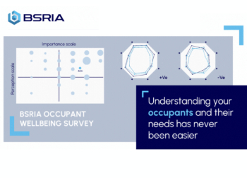
Occupant satisfaction and wellbeing tool inc. physical environment, indoor facilities, functionality and accessibility.

Preserving, waterproofing and decorating buildings.

Many resources for visitors aswell as new features for members.
Using technology to empower communities

The Community data platform; capturing the DNA of a place and fostering participation, for better design.
Heat pump and wind turbine sound calculations for PDRs

MCS publish updated sound calculation standards for permitted development installations.
Homes England creates largest housing-led site in the North

Successful, 34 hectare land acquisition with the residential allocation now completed.
Scottish apprenticeship training proposals

General support although better accountability and transparency is sought.
The history of building regulations

A story of belated action in response to crisis.
Moisture, fire safety and emerging trends in living walls

How wet is your wall?

Current policy explained and newly published consultation by the UK and Welsh Governments.
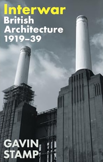
British architecture 1919–39. Book review.
Conservation of listed prefabs in Moseley.

Energy industry calls for urgent reform.
Comments
[edit] To make a comment about this article, click 'Add a comment' above. Separate your comments from any existing comments by inserting a horizontal line.