Cooling tower design and construction
For more information, see Cooling tower.
Contents |
[edit] Introduction
Cooling towers reject heat through the evaporation of water in a moving air stream within the cooling tower. The temperature and humidity of the air stream increases through contact with the warm water, and this air is then discharged. The cooled water is collected at the bottom of the tower.
Cooling towers were invented during the industrialisation of the 19th century through the development of condeners for use with the steam engine. By the early 20th century, advances in cooling towers were fueled by the rapidly growing electric power industry. Where there were areas of available land, the systems took the form of cooling ponds, whereas in city areas they were cooling towers, either positioned on building rooftops or as free-standing structures.
[edit] Hyperboloid structure
Hyperboloid structures are often designed as tall towers, where the strength of the hyperboloid’s geometry is used to support an object high off the ground. They have superior stability and resistance to external forces than ordinary structures; however, the drawback is the shape resulting in low space efficiency. This means they are most suited to purpose-driven structures such as cooling towers.
The hyperboloid shape is particularly suited to cooling tower construction as the wide base provides a large space for the water and cooling system. The narrowing effect of the tower helps with the laminar flow of the evaporated water as it rises. As the tower widens out at the top, it supports the turbulent mixing as the heated air makes contact with the atmospheric air.
The first hyperboloid structure was a 37-metre lattice water tower, built in 1896 for the All-Russian Exhibition located in Pilibino, Russia.
Dutch engineers Frederik van Iterson and Gerard Kuypers patented the hyperboloid cooling tower in 1918, with the first being built near Heerlen that year. The UK saw the first tower being built in 1924 in Liverpool, to cool water used at a coal-fired electrical power station.
[edit] Construction
Cooling towers can be small-scale roof-top installations, medium-sized packaged units, or very large structures sometimes associated with industrial processes or power stations with their characteristic plume of water vapour in the exhaust air.
These large cooling towers can be up to 200 metres (660 ft) tall and 100 m (320 ft) in diameter. They are often constructed as hyperboloid, doubly-curved concrete shell structures supported on a series of concrete struts. The foundations typically consist of an inclined pond wall forming a circular ‘tee’ beam with a wide concrete strip. The beam acts to resist the lateral load of the tower’s shell structure. As well as the ‘tee’ beam, piled foundations are normally required to minimise differential settlement and reduce the risk of cracking.
The cooling system is housed in the tower’s base which is typically the bottom 10 metres, the rest of the tower consisting of an empty shell. The water falls and collects in a pond at the base of the tower, formed by a base slab and the pond wall.
In natural-draught cooling towers the open structure at the base allows a natural movement of air. Mechanical-draught cooling towers use fans to provide a draught, where it is necessary to maintain or not exceed a fixed temperature level. The costs associated with the operation of mechanical-draught may be higher, but it is more efficient than natural draught.
[edit] Find out more
[edit] Related articles on Designing Buildings Wiki
- Air handling unit.
- Bridge construction.
- Caisson.
- Civil engineer.
- Cofferdam.
- Cooling.
- Cooling tower.
- Dam construction.
- Driven piles.
- Evaporative cooling.
- Grouting in civil engineering.
- HVAC.
- Institution of Civil Engineers ICE.
- Marine energy and hydropower.
- Pile foundations.
- Refrigerants.
- Skyfarm.
- Structural engineer.
- Tunnelling.
- Water engineering.
[edit] External references
- ‘Introduction to Civil Engineering Construction’ (3rd ed.), HOLMES, R., The College of Estate Management (1995)
Featured articles and news
The history of building regulations
A story of belated action in response to crisis.
Moisture, fire safety and emerging trends in living walls
How wet is your wall?
Current policy explained and newly published consultation by the UK and Welsh Governments.
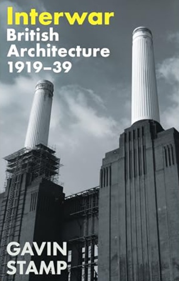
British architecture 1919–39. Book review.
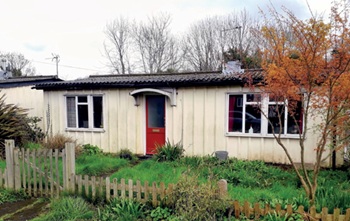
Conservation of listed prefabs in Moseley.
Energy industry calls for urgent reform.
Heritage staff wellbeing at work survey.
A five minute introduction.
50th Golden anniversary ECA Edmundson apprentice award
Showcasing the very best electrotechnical and engineering services for half a century.
Welsh government consults on HRBs and reg changes
Seeking feedback on a new regulatory regime and a broad range of issues.
CIOB Client Guide (2nd edition) March 2025
Free download covering statutory dutyholder roles under the Building Safety Act and much more.
AI and automation in 3D modelling and spatial design
Can almost half of design development tasks be automated?
Minister quizzed, as responsibility transfers to MHCLG and BSR publishes new building control guidance.
UK environmental regulations reform 2025
Amid wider new approaches to ensure regulators and regulation support growth.
The maintenance challenge of tenements.
BSRIA Statutory Compliance Inspection Checklist
BG80/2025 now significantly updated to include requirements related to important changes in legislation.


