Thermal storage for cooling
Contents |
[edit] Introduction
Ice can be used as an effective means of thermal storage, storing ‘coolth’ in colder parts of the day to provide cooling during warmer parts of the day. Thermal storage for cooling can be a useful way of achieving efficiency and carbon emission reductions in climates with wide daily temperature variations, especially in areas where water is not available for heat rejection. It can also be a useful way of gaining utility incentives and reducing peak demand charges.
[edit] Design considerations
For ice storage systems, the heat absorption rate of the system is reduced as more of the ice is melted. The capacity of the system should factor in when the peak heat absorption rate is required as the stored energy is used. It may not be detailed enough to integrate the load profile over the period for which storage will be used and size the system on that alone. The storage system may end up undersized as a result.
Chillers that will be used to build ice as well as directly cool loads should be specified with electronic expansion valves rather than mechanical thermal expansion valves to enable easy switching between evaporator temperature set points. This is a bigger issue with smaller, non-VFD chillers (variable frequency drive) and modular chillers where a TXV (thermal expansion valve) will be the standard.
Wet bulb temperatures vary over a narrower range than dry bulb temperatures so with water-cooled systems the carbon benefits are seen on the electric utility side where efficient base load powerplants shoulder a higher load than inefficient "peaking" power plants.
Ice storage is not applicable to absorbers. Ice storage may however be applied in parallel with absorbers. Chilled water storage may be applicable to absorbers which are waste heat fired absorbers. Solar fired absorbers are probably not the best application for storage unless a design were to be considered without any other refrigeration technology. It might be more efficient to store the excess energy in such a system as heated fluid before it is used by the absorbers.
[edit] Ice storage sizing
The total installed chiller capacity (both glycol and conventional) for an ice system should be around 65% of the total peak cooling load. This will however depend entirely on the load profile. The purpose of using conventional chillers is to meet the base load ie the consistent load that exists right through the night, this also simplifies control as there is no simultaneous ice building and direct cooling. An example of a load profile is shown below.
The blue represents the baseload chiller. The nature of the buildings means that the night time load is a very small percentage of the peak load and so in this case, there is only one conventional baseload chiller rated at 3900kW. The purple/mauve colour represents the glycol (ice) chillers in charging mode, building ice. The light blue represents the glycol chillers operating in direct cool mode, the dark blue is then the ice being harvested to meet the peak load.
In this case, there were four ice chillers each at around 3800kW arranged in modules, which is how they achieve the simultaneous cooling and ice building at 0:00. Thus the ice chillers ran during the day; the glycol did not affect the COP (coefficient of performance) too much as they ran at normal temperatures during the day. The capacity was derated due to the heat transfer reduction of the glycol, but the actual efficiency may only have reduced by about 10%. When they reduced to operate in night mode the output was always derated, usually around 60% but the efficiency again was still good because of the cooler night time temperatures.
The split between baseload and ice chillers is highly dependent upon load profile but it will range typically from around 25-50% baseload chiller. For a 24 hour operating building it will be closer to 50%.
In terms of overall energy savings, they are most effective when using air cooled chillers when there is a peak diurnal range of at least 10°C. Another good way to improve efficiency is to harness a large delta T; use the chillers to precool the water at a higher than usual temperature 15-8° and then go through ice to go from 8-3. This means that the chiller operates at more favourable conditions. Then consider the operating savings connected to fans and pumps. This means the overall savings are not easy to predict without a significant amount of detail, but with air cooled chillers there will be savings.
All of this assumes the use of a peak lopping system which gives optimum capital expenditure (capex). Using a full storage system is more efficient as all cooling occurs at night but the capex is much higher as there will generally need to be more chillers than a conventional system in addition to the ice.
Finally in terms of space, ice storage systems don’t save huge amounts on the central plant, the ice tanks do need space but the chiller farm size is reduced (which would be difficult to hide architecturally). This is particularly true for large air-cooled plants. There are then space savings from the large delta T and low temperature which reduces ducts/pipes and airhandling plant.
This article was created by --Buro Happold.
[edit] Related articles on Designing Buildings Wiki
- Dynamic thermal modelling of closed loop geothermal heat pump systems.
- Earth-to-air heat exchangers.
- Geothermal energy.
- Geothermal pile foundations.
- Ground energy options.
- Ground pre-conditioning of supply air.
- Ground source heat pumps.
- Night-time purging.
- Phase change materials.
- Thermal labyrinths.
- Thermal mass.
- Thermal storage for cooling.
[edit] External references
- Calmac http://www.calmac.com/
- Cryogel http://www.cryogel.com/
- Balitomore Air Coil http://www.baltimoreaircoil.com/
Featured articles and news
Sir John Betjeman’s love of Victorian church architecture.
Exchange for Change for UK deposit return scheme
The UK Deposit Management Organisation established to deliver Deposit Return Scheme unveils trading name.
A guide to integrating heat pumps
As the Future Homes Standard approaches Future Homes Hub publishes hints and tips for Architects and Architectural Technologists.
BSR as a standalone body; statements, key roles, context
Statements from key figures in key and changing roles.
ECA launches Welsh Election Manifesto
ECA calls on political parties 100 day milestone to the Senedd elections.
Resident engagement as the key to successful retrofits
Retrofit is about people, not just buildings, from early starts to beyond handover.
Plastic, recycling and its symbol
Student competition winning, M.C.Esher inspired Möbius strip design symbolising continuity within a finite entity.
Do you take the lead in a circular construction economy?
Help us develop and expand this wiki as a resource for academia and industry alike.
Warm Homes Plan Workforce Taskforce
Risks of undermining UK’s energy transition due to lack of electrotechnical industry representation, says ECA.
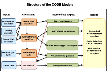
Cost Optimal Domestic Electrification CODE
Modelling retrofits only on costs that directly impact the consumer: upfront cost of equipment, energy costs and maintenance costs.
The Warm Homes Plan details released
What's new and what is not, with industry reactions.
Could AI and VR cause an increase the value of heritage?
The Orange book: 2026 Amendment 4 to BS 7671:2018
ECA welcomes IET and BSI content sign off.









Comments
To start a discussion about this article, click 'Add a comment' above and add your thoughts to this discussion page.