


How to layout a building

Contents |
[edit] What is setting out?
Setting out a building is the process of transferring design proposals from drawings onto the ground. It establishes the location points for site boundaries, foundations, columns, centre-lines of walls and other necessary structural parts. It also establishes the buiding's correct extent, angle and level.
The whole structure will be located and constructed according to the initial setting out. Accurate setting out is therefore a fundamental part of construction works, and errors can be very expensive and time consuming to correct. It should only be undertaken by competent persons, and all work should be thoroughly checked, preferably by different personnel before construction begins.
Setting out is usually undertaken once the site has been subject to a condition survey and desk study, and has been cleared of any debris, unwanted vegetation or other obstructions. Works necessary to create the required levels may also have been completed before the setting out process begins.
The position and orientation of the structure is generally described in an architect's or engineer’s drawings, defining precisely how the layout should be arranged. Controlling dimensions and references on the plans will determine the positioning of the building, and in particular its foundations. These include; overall length and width, distances to road centre-lines and to other structures, internal structural measurements and so on.
The controlling points of the structure can then be marked so that the construction team can easily identify them. This usually consists of marking the building’s corners, horizontal and vertical positions, using stakes, batter boards with string lines, drill holes, cut-and-fill notations, and other methods.
[edit] What is a temporary bench mark (TBM)?
A temporary bench mark is a fixed point with a known elevation, usually ground floor level. This should be established at an early stage. It is the fixed point to which all levels are related. Where possible the TBM should relate to an ordnance bench mark. On the site, it could relate to any permanent fixture, such as a manhole cover or firmly-driven post. Typically, it is signified by a peg or steel angle that is conveniently located (eg near the site office) and concreted in or fenced off with low-level timber.
As minus signs are easily misread, the TBM position should enable all other levels to be positive. The TBM should be clearly indicated on all drawings, with all levels and vertical dimensions expressed in metres to three decimal places in relation to it.
[edit] What is the baseline?
Typically the first layout task is establishing a baseline to which all the setting out can be related. The baseline is a straight reference line in respect to which the building’s corners are located on the ground. It often coincides with the ‘building line’, which is the boundary of the area, or the outer boundary of a road or curb, often demarcated by the local authority.
[edit] Horizontal controls
Horizontal controls are points that have known coordinates with respect to a specific point. Other points such as layout corners can then be located. Numerous control points should be used so that each point on the plan can be precisely located on the ground.
[edit] Vertical controls
Vertical controls enable design points to be positioned at their correct levels. The vertical control points are established relative to specified vertical datum – often a timber post set in concrete. But it can also be a specific height from a nearby road or land feature.
Horizontal and vertical controls are generally established during the levelling phase using a theodolite or similar instrument.
Levels on site-layout plans should be denoted in metres to three decimal places, eg 32.350. Also, intended levels should be written in a box, while existing levels can be written normally. An 'x' or '+' should be used on plans to denote the exact point to which a level applies
[edit] Building layout
For a simple building layout, such as a rectangle, the outline of the building is marked by a line tied to corner posts - a nail in the top of the post can be used to attach the line to. A theodolite, site square or builder’s square is used to turn off 90-degree angles for the remaining corners. Ranging rods may be required to establish a straight line between corner posts.
Corner posts are usually 50 x 50mm timber posts driven firmly into the ground, with a nail in the post’s centre. The outline may be marked on the ground with dry lime or similar powder. Timber profile boards can be used at the corners. Profile boards are typically between 0.6-1m in height and comprise two 50 x 50mm posts driven at least 600mm into the ground, with a 150 x 38mm crossboard.
Where the outline of a building is more complex than a simple rectangle, it may be necessary to establish a range of points in the same way as for laying out a simple rectangle. However, great care is required, as small errors are more likely to be introduced as more points are positioned. Often the easiest way of laying out an irregular building shape is to first lay out a large rectangle which will enclose the entire building or the greater part of it. Once this is done, deductions and alterations can be made to obtain the precise layout required.
[edit] Trenches
The layout of trenches establishes the excavation size, shape and direction, as well as the width and position of walls. Trenches are excavated once the building outline has been set out. The width is often marked with a line of dots of dry lime powder for accurate excavation by hand, whereas the centre line is marked for accurate machine excavation.
Outline profile boards are often used to control trench positioning, width and depth. In order that they do not obstruct the excavation work, profile boards should be set up at least 2m clear of the trench positions. The level of the profile crossboard should be related to the site datum and fixed at a convenient height above ground level, often with cords strung between two profiles at either end of the trench. Bands can be painted on the crossboard for identification purposes.
Pegs are often driven into the bottom of the trench to mark the top of the concrete strip that is subsequently poured.
The corners of walls are transferred from intersecting cord lines to mortar spots on the concrete foundations, using a spirit level for accuracy.
The cutting of trenches needs to be undertaken with great care, especially if they are to be left open for an extended period as there is the possibility of the sides caving in.
[edit] Reduced level excavations
The overall outline of a reduced level area can be set out working from a baseline. Corner posts are fixed to the outline of the excavation area and the outline marked with dry sand or similar material. To control the depth of the excavation, sight rails are set up at a convenient height and at positions which will enable a traveller to be used.
A traveller is a profile board with a fixed height, used for controlling excavated levels between profile boards. By placing the traveller in the sightline between two level boards, it is possible to see whether or not the excavation has been carried out to correct levels. The height of the traveller is the desired level of the sight rail minus the formation level of the excavated area.
[edit] Framed building
Framed buildings are usually related to a grid, often set out from a baseline. The intersections of the grid lines mark the centre points for isolated or pad foundations.
The layout of the grid is established using a theodolite and the grid intersections marked using pegs. Once the grid has been set out, offset pegs or profiles can be fixed clear of any subsequent excavation work. Control of excavation depth can be by means of a traveller sighted between sight rails or by level and staff related to a site datum.
[edit] Related articles on Designing Buildings
- Building survey.
- Datum.
- Land surveying.
- Laser scanning.
- Levelling.
- Measurement of existing buildings.
- Ordnance Datum.
- Road construction.
- Setting out roads.
- Site layout plan.
- Site plan.
- Site surveys.
- Surveying instruments.
- Surveyor.
[edit] External references
- CivilEBlog - Building layout
- 'Building Construction Handbook' (6th ed.). CHUDLEY, R., GREENO, R., Butterworth & Heinemann (2007)
Featured articles and news
Costs and insolvencies mount for SMEs, despite growth

Construction sector under insolvency and wage bill pressure in part linked to National Insurance, says report.
The place for vitrified clay pipes in modern infrastructure
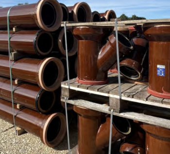
Why vitrified clay pipes are reclaiming their role in built projects.

Research by construction PR consultancy LMC published.
Roles and responsibilities of domestic clients
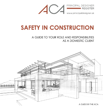
ACA Safety in Construction guide for domestic clients.
Fire door compliance in UK commercial buildings
![]()
Architect and manufacturer gives their low down.
Plumbing and heating for sustainability in new properties

Technical Engineer runs through changes in regulations, innovations in materials, and product systems.
Awareness of the Carbon Border Adjustment Mechanism
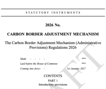
What CBAM is and what to do about it.
The new towns and strategic environmental assessments
12 locations of the New Towns Taskforce reduced to 7 within the new towns draft programme and open consultation.
Buildings that changed the future of architecture. Book review.
The Sustainability Pathfinder© Handbook
Built environment agency launches free Pathfinder© tool to help businesses progress sustainability strategies.

Government outcome to the late payment consultation, ECA reacts.
IHBC 2025 Gus Astley Student Award winners
![]()
Work on the role of hewing in UK historic conservation a win for Jack Parker of Oxford Brookes University.
Future Homes Building Standards and plug-in solar

Parts F and L amendments, the availability of solar panels and industry responses.
How later living housing can help solve the housing crisis
Unlocking homes, unlocking lives.
Preparing safety case reports for HRBs under the BSA
A new practical guide to preparing structural inputs for safety cases and safety case reports published by IStructE.
Male construction workers and prostate cancer

CIOB and Prostate Cancer UK encourage awareness of prostate cancer risks, and what to do about it.
Comments
[edit] To make a comment about this article, click 'Add a comment' above. Separate your comments from any existing comments by inserting a horizontal line.